Material distributing screening machine

A screening machine and fabric distribution technology, which is applied in the direction of filter screen, solid separation, grille, etc., can solve the problems of poor impact resistance of bulk materials, inability to remove materials, uneven distribution, etc., and achieve easy maintenance, high screening rate, even cloth effect

Active Publication Date: 2011-11-23
SICHUAN ZHONGMENG ELECTRIC POWER EQUIP MFG CO LTD
View PDF5 Cites 12 Cited by
  • Summary
  • Abstract
  • Description
  • Claims
  • Application Information

AI Technical Summary

Problems solved by technology

[0011] The purpose of the present invention is to solve the deficiencies of the prior art and provide a high-efficiency distribution screening machine to solve the problems of low screening efficiency, poor impact resistance of bulk materials, and blockage

Method used


Image

  • Material distributing screening machine
  • Material distributing screening machine
  • Material distributing screening machine

Examples


Embodiment 1

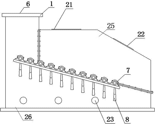
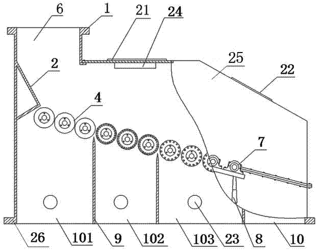
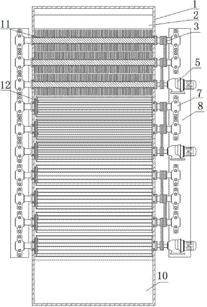
[0047] Example 1: Combining figure 1 , Figure 9 , Figure 10 , Figure 4 , Figure 5 Describe this embodiment, the material distribution screening machine, it comprises casing 1, forced distribution plate 2, transmission device 3, filter drum 4, deceleration motor 5, the top of casing 1 is provided with feeding port 6, and forced distribution plate 2 is located at On the casing 1 below the feed inlet 6, the forced distribution plate 2 is installed on the flange plate drum 11, and is located in the material falling channel. The angle between the forced distribution plate 2 and the falling channel is less than 90°. It is made of wear-resistant and impact-resistant material, and the wear-resistant material of the forced cloth plate can be replaced. There are 14 filter drums 4 installed in the casing 1, and the two ends of each filter drum 4 are installed on the bearing housing 7, and the bearing housing 7 is fixed on the support frame 8 on both sides of the outer casing 1, a...

Embodiment 2

[0052] Example 2: Combining figure 1 , figure 2 , Figure 11 , Figure 4 , Figure 5 Describe this embodiment, the material distribution screening machine, it comprises casing 1, forced distribution plate 2, transmission device 3, filter drum 4, deceleration motor 5, the top of casing 1 is provided with feeding port 6, and forced distribution plate 2 is located at On the casing 1 below the feed inlet 6, the forced distribution plate 2 is installed on the flange plate drum 11, and is located in the material falling channel. The angle between the forced distribution plate 2 and the falling channel is less than 90°. It is made of wear-resistant and impact-resistant material, and the wear-resistant material of the forced cloth plate can be replaced. There are 20 filter drums 4 installed in the casing 1, and the two ends of each filter drum 4 are installed on the bearing housing 7, and the bearing housing 7 is fixed on the support frame 8 on both sides of the outer casing 1, a...


PUM

PropertyMeasurementUnit
Diameteraaaaaaaaaa

Abstract

The invention discloses a material distributing screening machine, comprising a machine case (1), a forced fabric plate (2), a driving device (3), a filtering roller (4), a reducer motor (5) and an iron removing device (24), wherein the machine case (1) is provided with a feeding hole (6) and a plurality of discharging holes (10), the filtering roller (4) comprises a flange disk type roller (11) and a filtering rope type roller (12), the filtering roller (4) is provided with the driving device (3), the reducer motor (5) drives the filtering roller (4) to rotate by virtue of the driving device (3), and material enters from the feeding hole (6), is screened by the filtering roller (4) and is discharged by the discharging hole (10). The invention has the beneficial effects that: more than two materials in different grain sizes can be screened by setting different interstitial screen cuts, the working condition requirement for screening more than two materials can be met, screening efficiency is high, bulk material impact resistance is high, material is distributed more uniformly, no blockage is caused, and an iron piece contained in the material can be removed.

Description

technical field [0001] The invention relates to a coal coarse and fine material separation device, in particular to a cloth screening machine. Background technique [0002] The fuel of circulating fluidized bed boilers in thermal power plants is coal gangue with a certain particle size. The particle size of coal from coal mines is uneven, but most of the materials do not need repeated crushing. These materials generally account for about 35% of the entire material. 75%. If this part of the qualified particle size material directly enters the follow-up crushing equipment without being screened out by the sieve distribution equipment, it will have negative effects on the combustion of the follow-up crusher and boiler in the following aspects: 1. The crusher runs for a long time with overload, The power consumption increases, and the service life of the motor is shortened; 2. The large amount of over-crushing directly affects the combustion efficiency of the boiler; 3. The int...

Claims


Application Information

Patent Timeline
IPC IPC(8): B07B1/15B07B1/46B07B1/42B07B15/00
Inventor 马琳
Owner SICHUAN ZHONGMENG ELECTRIC POWER EQUIP MFG CO LTD
Why Eureka
Try Eureka