
Relief angle adjustable device for automatic grinding of arc-edge diamond lathe tool

A grinding device and diamond technology, which is applied in other manufacturing equipment/tools, manufacturing tools, etc., can solve problems such as low production efficiency, difficulty in diamond turning blade shape accuracy and tool angle, and greater influence of human subjective factors, so as to avoid The effect of secondary clamping error, reducing production cost and improving manufacturing accuracy

Inactive Publication Date: 2013-01-30
TIANJIN UNIV
View PDF2 Cites 0 Cited by
  • Summary
  • Abstract
  • Description
  • Claims
  • Application Information

AI Technical Summary

Problems solved by technology

[0004] However, most of the grinding of single crystal diamond turning tools in the world is still done manually by skilled technicians, which is greatly affected by human subjective factors.
During the machining process, the confirmation of the edge shape accuracy of the cutting edge and the clearance angle of the tool is mainly carried out by off-line measurement of projectors, microscopes, and non-contact shape measuring devices, etc., due to the influence of human subjective factors and errors caused by repeated clamping , so it is difficult to ensure that the processed diamond turning tool has a stable edge shape accuracy and tool angle, and the production efficiency is also very low
As a result, the current single crystal diamond turning tool is far from meeting the market demand in terms of accuracy and delivery cycle, and the accuracy and efficiency of the current single crystal diamond turning tool blade grinding are difficult to meet the market demand

Method used


Image

  • Relief angle adjustable device for automatic grinding of arc-edge diamond lathe tool
  • Relief angle adjustable device for automatic grinding of arc-edge diamond lathe tool
  • Relief angle adjustable device for automatic grinding of arc-edge diamond lathe tool

Examples


Embodiment Construction

[0013] The present invention will be described in detail below in conjunction with the accompanying drawings and specific embodiments.

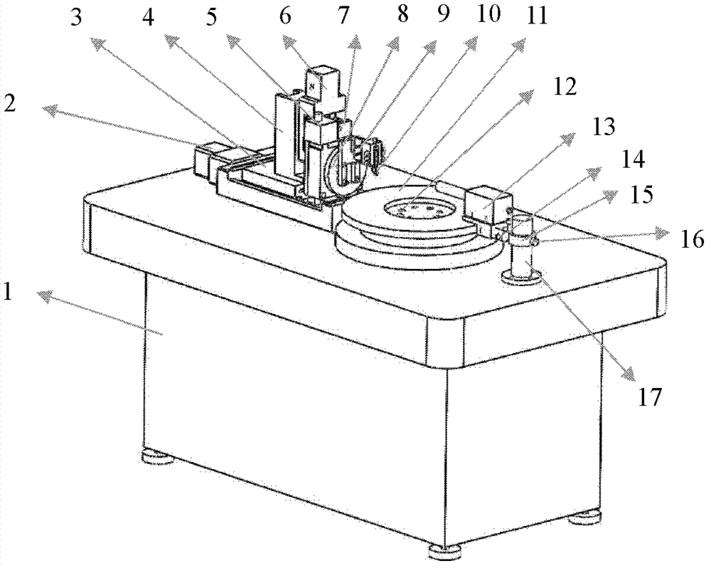
[0014] The invention is a novel diamond turning tool manufacturing device invented based on the diamond turning tool shape creation mechanism and the material properties of diamond. The shown device consists of a base 1, a transverse feed device including a transverse feed table 3 and a drive motor 2, a longitudinal feed device including a longitudinal feed table 7 and a drive motor 6, and a swing device including a swing table 8 It is composed of a drive motor 5 connected to the swing table 8, an adjustable back angle clamp 10, a grinding disc (or end face grinding wheel) 11, a CCD (charge coupled device) camera 13, and a computer. The said transverse feed device and longitudinal structure device can adopt structures such as lead screw nut slide table and also can adopt the structure of cylinder push rod slide table.

[0015] like figure 1...


PUM


Abstract

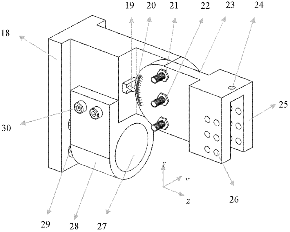
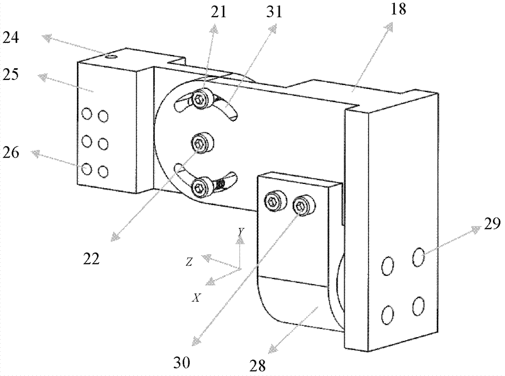
The invention discloses a relief angle adjustable device for the automatic grinding of an arc-edge diamond lathe tool, comprising a base, wherein a driving device, a grinding disc and a photographing device are sequentially installed on the table board of the base; the driving device comprises a transverse feed device and a longitudinal feed working table connected with the transverse feed device; a longitudinal feed device is arranged on the longitudinal feed worktable; a swing device is connected with the longitudinal feed device; a relief angle adjustable fixture comprises a cantilever part connected with the swing device; the center of one side of an angle adjusting part and the center of the front end of the cantilever part are connected through a shaft and can rotate around the shaft at a certain rotation angle; the rotation angle can be displayed through a reading device; a lathe tool clamping part on which a groove is arranged is connected with one side of the angle adjusting part; and the diamond lathe tool arranged on a tool holder is inserted in and connected with the groove. By utilizing the device provided by the invention, the relief angle of the lathe tool can be accurately adjusted when the arc-edge diamond lathe tool is ground.

Description

technical field [0001] The invention relates to an automatic grinding device, in particular to an automatic grinding device for a circular arc edge diamond turning tool. Background technique [0002] In recent years, with the development of ultra-precision machining technology, the demand for aspheric and free-form surfaces of optical functional crystal materials with soft and brittle properties has gradually increased. Soft and brittle functional crystal materials have excellent optical, electrical and other physical properties, and have important application prospects in the fields of optics and energy. However, their anisotropy, soft and brittle, and deliquescence characteristics make them extremely difficult to process The machining requirements of precision, high surface integrity, and highly complex shapes make the existing ultra-precision machining technology face new challenges. At present, the method of ultra-precision turning using a single-crystal diamond turning...

Claims


Application Information

Patent Timeline
Patent Type & Authority Patents(China)
IPC IPC(8): B23P23/06
Inventor 仇中军丁立宇李振涛房丰洲
Owner TIANJIN UNIV
Learn More