Random polishing track motion method for restraining track error

A trajectory movement and trajectory technology, which is applied in the field of optical manufacturing of lithography objective lenses, can solve the problems of high performance requirements of machine tools and difficult realization, and achieve the effect of improving precision and convenient operation

Inactive Publication Date: 2011-11-23
INST OF OPTICS & ELECTRONICS - CHINESE ACAD OF SCI
View PDF4 Cites 20 Cited by
  • Summary
  • Abstract
  • Description
  • Claims
  • Application Information

AI Technical Summary

Problems solved by technology

However, this pseudo-random trajectory movement method has extremely high requirements on the performance of the machine tool, and it is not easy to realize in actual processing.

Method used


Image

  • Random polishing track motion method for restraining track error
  • Random polishing track motion method for restraining track error
  • Random polishing track motion method for restraining track error

Examples


Embodiment Construction

[0016] In order to make the object, technical solution and advantages of the present invention clearer, the present invention will be described in further detail below in conjunction with specific embodiments and with reference to the accompanying drawings.

[0017] combine figure 1 Shown the flow chart of the inventive method, below only with a piece of optical element to be polished is the quartz plane glass of Φ 30mm as an example, this example is as follows to the specific implementation steps of realizing the inventive method:

[0018] Step 1: Discretize the error distribution of the quartz flat glass surface to be polished with 30×30 grid data points. The discrete points are evenly distributed on the surface of the optical element to be polished. The discrete data points are the points to be polished by the polishing head.

[0019] Step 2: Calculate and determine the residence time distribution on the quartz glass surface according to the removal function distribution an...


PUM


Abstract

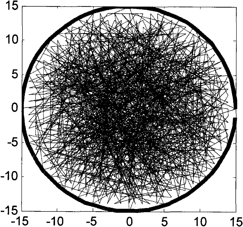
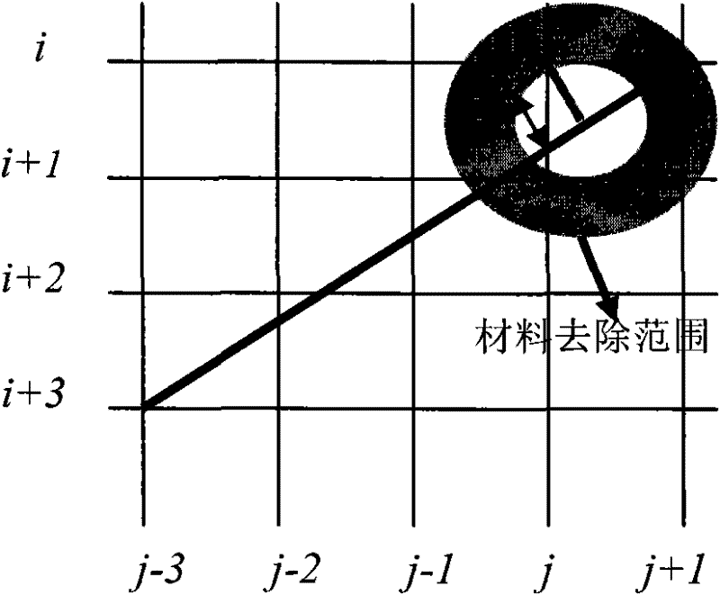
The invention relates to a random polishing track motion method for restraining a track error, which comprises the following steps: confirming to-be-polished points and residence time distribution on a surface of a to-be-polished optical element and utilizing a random track algorithm to generate a polishing sequence and a polishing track of dispersed points on the surface of the to-be-polished optical element; utilizing a residence time compensation method to calculate the residence time distribution for a polishing head motion track to pass through by the polishing points, thereby acquiring the accurate residence time of the dispersed points on the surface of the to-be-polished optical element; generating a random track numerical control polishing program code by a machine tool code conversion program according to the residence time distribution; and polishing all the points on the surface of the to-be-polished optical element by executing the random track numerical control polishingprogram code on a numerical control polishing machine tool. A random track polishing method is used for enabling the motion tracks of the polishing head and polishing grains to approach to random litter distribution according to surface figure distribution, thoroughly removing regular track scratches from the to-be-polished optical element, uniformly spreading the removal function iteration errors among regular tracks on the whole surface figure, and promoting the surface figure accuracy.

Description

technical field [0001] The invention belongs to the technical field of optical manufacturing of lithography objective lenses, is applied in the polishing process of optical elements in a lithography system, and relates to a novel polishing trajectory movement method. Background technique [0002] The key equipment for microelectronics is an important support for microelectronics technology. The lithography objective lens is the key core part of the distributed and repeated projection lithography of special equipment for microelectronics. D. The quality requirements of lithography objective optical components are an order of magnitude higher than other high-precision optical components. For example, the radius of curvature is less than or equal to 1 μm, the surface error is less than or equal to λ / 20~λ / 100, and the rms root mean square value is less than or equal to It is equal to λ / 100~λ / 300, etc., and puts forward extremely strict requirements on the accuracy of the outer ...

Claims


Application Information

Patent Timeline
Patent Type & Authority Applications(China)
IPC IPC(8): B24B13/00
Inventor 施春燕袁家虎伍凡万勇建范斌雷柏平
Owner INST OF OPTICS & ELECTRONICS - CHINESE ACAD OF SCI
Why Eureka
Try Eureka