
Polishing grinder

A polishing grinding and aperture technology, applied in the direction of optical surface grinders, grinding/polishing equipment, grinding machines, etc., can solve the problems of insufficient grinding amount, long processing time, medium and high surface shape, etc., and achieve the purpose of suppressing the change of the surface shape of the abrasive tool, Prevents scratches on the surface of parts and improves polishing efficiency

Inactive Publication Date: 2011-11-23
CDGM OPTICAL GLASS +1
View PDF5 Cites 8 Cited by
  • Summary
  • Abstract
  • Description
  • Claims
  • Application Information

AI Technical Summary

Problems solved by technology

[0004] The disadvantages of the above-mentioned polishing abrasives are: 1) the effective utilization rate of the polyurethane sheet is low during cutting and pasting, which wastes materials; 2) the partial coverage ratio of the polyurethane sheet on the polishing matrix cannot be adjusted. In the process of processing, the grinding efficiency of optical parts is low under the same process conditions, especially when processing hard material parts, the processing time is long, the amount of grinding is insufficient, and the appearance of pitting is easy to occur Defects; 3) When processing optical parts, according to the common sense of optics, when the designed abrasive tool meets "cosine wear", the radius of curvature of the abrasive tool processing surface remains unchanged, and the aperture of the processed part is stable, but the surface of the above-mentioned polished abrasive tool The area distribution of polyurethane is difficult to meet the "cosine wear" and cannot meet the ideal surface stability requirements; 4) In the process of processing, the intake of polishing liquid is insufficient, and the polyurethane sheet is easily passivated, which affects the grinding efficiency, especially when processing similar hemispheres For optical components, because the polishing liquid cannot be taken into the center of the mold, it is easy to have a medium-high surface; 5) The heat dissipation effect is not good, and it is easy to cause burns or poor appearance of optical components such as frog skin; 6) The impurities generated during the polishing process cannot be completely Washed away by polishing fluid, prone to scratches and other defects

Method used


Image

  • Polishing grinder
  • Polishing grinder
  • Polishing grinder

Examples


Embodiment Construction

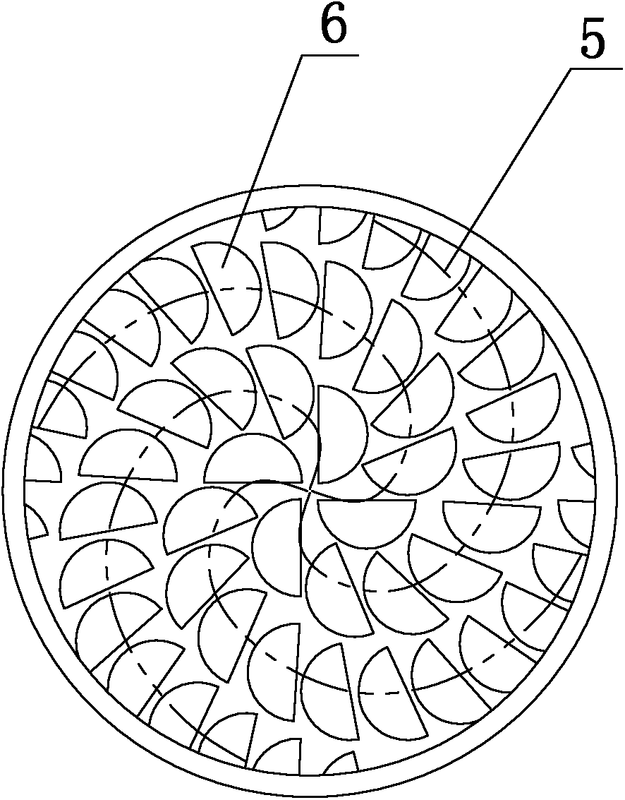
[0018] Such as image 3 and Figure 4 As shown, the present invention cuts the polyurethane sheet into small circles or small semicircles 6, wherein the radius of the small circles or small semicircles 6 is between 1mm and 10mm, and these small circles or small semicircles 6 are arranged according to the multi-head spiral The way of line 5 is pasted on the polishing base mold 1. If the small semicircle 6 is used, the direction of the cut surface of the small semicircle 6 always points to the axis of the polishing base mold 1, so that the polishing mold conforms to "cosine wear", image 3 Shown is the small half-circle 6 . Among them, the multi-headed spiral line refers to: two or more mutually symmetrical points do spiral motion along the spherical surface, and the axial displacement of the point is proportional to the corresponding angular displacement.

[0019] Above-mentioned small disc or small semicircle 6 can also be pasted on the polishing matrix 1 according to the mo...


PUM

PropertyMeasurementUnit
Thicknessaaaaaaaaaa
Thicknessaaaaaaaaaa
Thicknessaaaaaaaaaa

Abstract

The invention provides a mould of a polyurethane sheet which is high in effective use rate, high in polishing efficiency and stable in polishing modular surface. The polishing grinder comprises a polishing base mode on which the polyurethane sheet is adhered, and the polyurethane sheet is small wafers or small semi-wafers. Since the small polyurethane wafers or small semi-wafers are used for adhering the polishing grinder, the effective use area of the whole polyurethane sheet can be increased, the cost of the polyurethane can be saved, the use rate is improved by 20% in comparison with the traditional polyurethane sheet; since the small polyurethane wafers or small semi-wafers have big gas and are uniformly arranged, a polishing solution can easily enter each place of the polishing grinder to inhibit the generation of passivation condition and maintain the cutting force; the polishing grinder can sufficiently intake the polishing solution, and the pressure born by parts is increased under the same condition; and therefore, the cutting force is strong, the polishing efficiency is greatly improved and is more than 30% higher than the traditional form.

Description

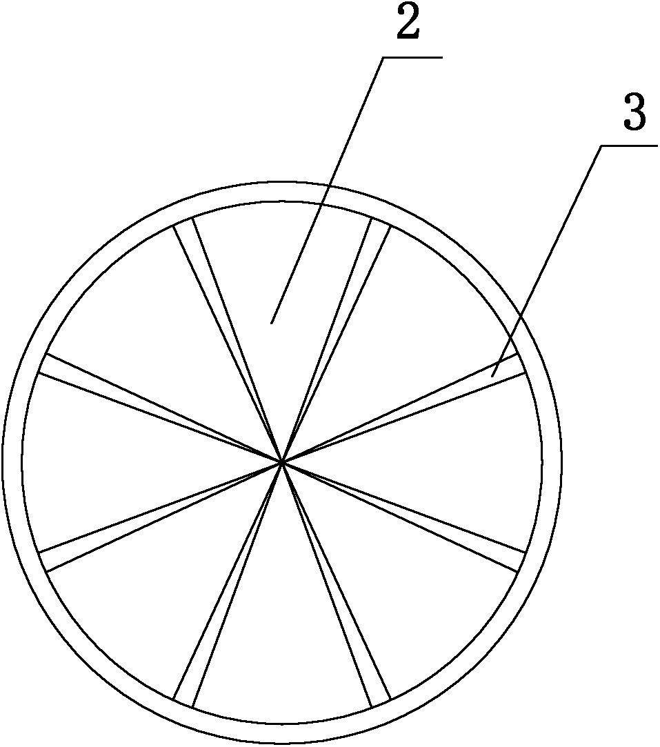
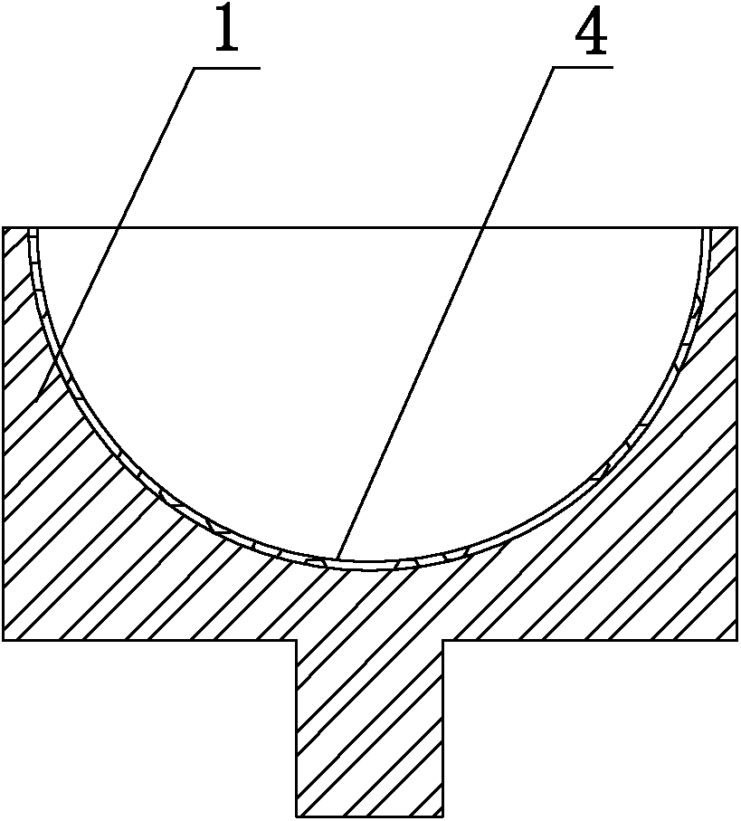
technical field [0001] The invention relates to a polishing abrasive, in particular to a high-speed polishing abrasive for optical elements. Background technique [0002] The structure of the current high-speed polishing abrasive tool is to select a suitable polyurethane sheet 2 according to the characteristics such as the material and caliber of the part to be processed on the polishing base mold 1, and cut the polyurethane sheet 2 into a fan, and paste it on the polishing base mold 1. On the surface 4, backflow grooves 3 are opened between polyurethane sheets 2 to form high-speed polishing abrasives, such as figure 1 and figure 2 As shown, the shape of the polishing abrasive can be concave, convex or flat, and the radius of curvature of the polishing abrasive can be arbitrarily selected according to the different parts. The figure shows a concave polishing mold. [0003] During the rotation of the abrasive tool, since the linear velocity of the edge is greater than the ...

Claims


Application Information

Patent Timeline
IPC IPC(8): B24B13/01
Inventor 李长勇
Owner CDGM OPTICAL GLASS
Learn More