Self-heating floor system and self-heating floor thereof

A self-heating, floor technology, applied in the field of building decoration, can solve problems such as hidden dangers, hidden dangers of safety, affecting heating and so on

Inactive Publication Date: 2011-11-23
葛跃进
View PDF9 Cites 16 Cited by
  • Summary
  • Abstract
  • Description
  • Claims
  • Application Information

AI Technical Summary

Problems solved by technology

The disadvantage of this electric heating floor system is that the power supply method using plugs and sockets between adjacent floors is unreliable. This is because the thickness of the floor is usually not more than 1.2 cm. Special plugs and sockets, even if the distance between the plugs and sockets is very short, a little carelessness will cause poor contact, which will not only affect normal heating, but also cause safety hazards
The electric heating floors in this document are powered in parallel. Although the failure of one electrical connection will cause the failure of all floors o

Method used


Image

  • Self-heating floor system and self-heating floor thereof
  • Self-heating floor system and self-heating floor thereof
  • Self-heating floor system and self-heating floor thereof

Examples


Embodiment 1

[0104] (Example 1, self-heating floor)

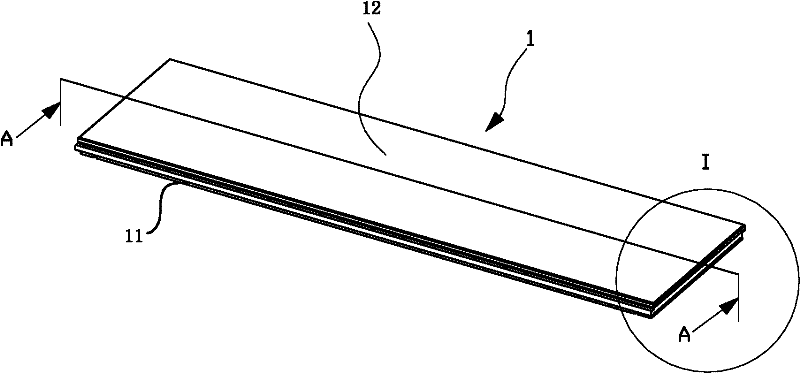
[0105] See Figure 1 to Figure 4 , Figure 8 and Figure 9 , The self-heating floor 1 of this embodiment includes a lower body 11 , an upper panel 12 , a heating sheet 13 and a plug assembly 14 .

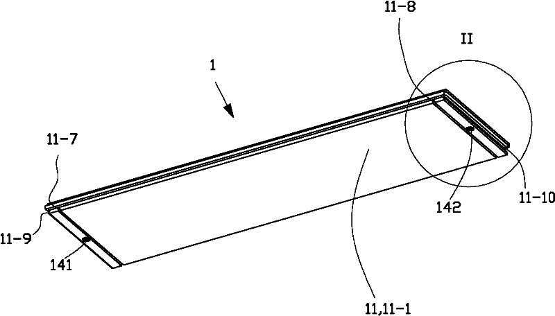
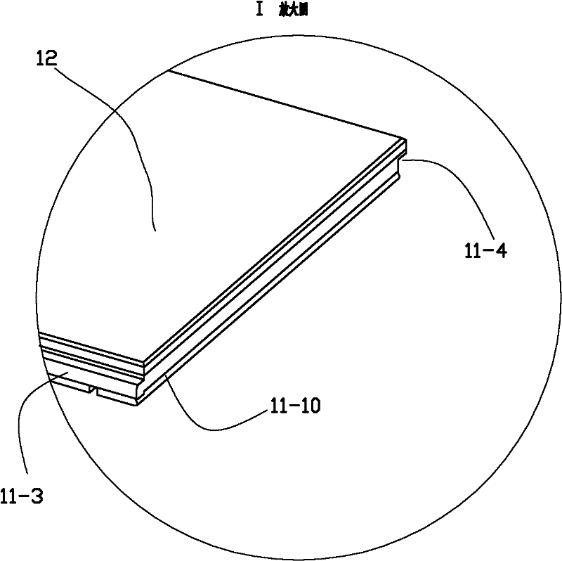
[0106] See figure 2 , Figure 4 and Figure 5 , the lower main body 11 is a homogeneous piece of wood, including a main body 11-1 with a basic shape of a cuboid, a tenon 11-3 located on the front side of the main body 11-1 and a tenon located on the rear side of the main body 11-1. The socket slot 11-4 and the socket tenon 11-3 are the parts that connect and cooperate with the socket slots of the self-heating floor adjacent to the front side during use, and the socket slot 11-4 is adjacent to the rear side during use. The parts where the joints of the self-heating floor are connected with each other.

[0107] See Figure 5 and Figure 9 , The lower main body 11 is also provided with an upper groove 11-2, 2 plug holes, 2 blocking and...

Embodiment 2

[0115] (Example 2, self-heating floor system)

[0116] See Figure 11 and Figure 12 , when describing the self-heating floor system in this embodiment, its front and rear, left and right, and up and down directions are the same as those described in Embodiment 1, that is, with Figure 11 The length direction of the mounting base 2 is the front-to-back direction, that is, Figure 12 The lower left in the middle is the front side, the upper right is the rear side, and the Figure 11 The up, down, left, and right directions of are the described up, down, left, and right directions.

[0117] See Figure 26 and Figure 27 , The self-heating floor system of this embodiment includes a self-heating floor, a mounting seat 2, a plugging blocking member 31, a plugging strip 32 and a power supply system. The power supply system includes a power supply line 600 and a keel line 400 . The self-heating floor adopts the self-heating floor 1 of Embodiment 1.

[0118] See Figure 11 , ...

Embodiment 3)

[0151] The rest of this embodiment is the same as Embodiment 1, the difference is that the self-heating floor 1 is also provided with a third plug assembly 14, and the plug assembly 14 is arranged at a position vertically arranged along the width direction of the self-heating floor 1 A quarter of the length of the self-heating floor 1 is at a symmetrical position on the plane, and the electric heater 13 of the self-heating floor 1 is provided with a corresponding electrode, and the corresponding position of the lower body 11 is provided with a corresponding electrode of the electric heater 13 groove. When in use, this self-heating floor 1 can be cut accordingly, and used in the corner of the room to be laid in the nail-free clip-on self-heating floor system in Embodiment 2.


PUM

PropertyMeasurementUnit
Depthaaaaaaaaaa
Thicknessaaaaaaaaaa

Abstract

The invention discloses a self-heating floor system and a self-heating floor thereof. The floor system comprises the self-heating floor, a mounting seat, an insertion stopper and a power supply system. The power supply system comprises a power supply circuit and keel circuits. The self-heating floor comprises a lower main body, an upper panel, electric heating plates and plug assemblies; and the electric heating plates are arranged between the lower main body and the upper panel, and two electrodes of the electric heating plates are hermetically and electrically connected with the corresponding plug assemblies. The mounting seat comprises a seat part and an insertion part; and the corresponding keel circuits and the insertion stopper are arranged in the insertion part. The self-heating floor is fixedly connected to the mounting seat through the corresponding insertion stopper on the mounting seat, and the plug assemblies are hermetically and electrically connected with the corresponding keel circuits respectively. The power supply circuit supplies power to each keel circuit, the corresponding keel circuits supply power to the corresponding electric heating plates, and the electrified electric heating plates emit heat to form the self-heating floor system.

Description

technical field [0001] The invention relates to a product in the field of building decoration, in particular to an electric heating floor system and the electric heating floor. Background technique [0002] At present, the form of self-heating floor is electric heating floor; electric heating floor has become a new heating method, which is to lay electric heating material under the floor, and heat the floor by heating the electric heating material. [0003] Chinese patent document CN1034826C (application number 92114554.3) discloses an electric heating floor. The floor is provided with two through holes in the horizontal direction in the floor board, and the electric heating wire is inserted into the through hole. The holes are dislocated and the heating wire is worn off, and the port of the through hole adopts a bell mouth. In order to be safer, the floor boards can be added with flame retardant materials, or the floor boards can be pressed with wood powder, asbestos powde...

Claims


Application Information

Patent Timeline
IPC IPC(8): E04F15/02E04F15/024F24D13/02
Inventor 葛跃进
Owner 葛跃进
Why Eureka
Try Eureka