Rudder direction changing impeller machine
A turbine and rudder technology, applied to engines, wind engines at right angles to the wind direction, mechanical equipment, etc., can solve the problems of small wind area and inability to make full use of energy, so as to improve utilization rate, make full use of energy, The effect of low resistance
- Summary
- Abstract
- Description
- Claims
- Application Information
AI Technical Summary
Problems solved by technology
Method used
Image

Examples
Embodiment Construction
[0022] Below in conjunction with accompanying drawing example, the present invention is described in further detail:
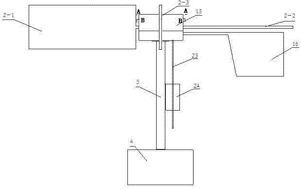
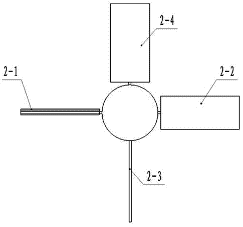
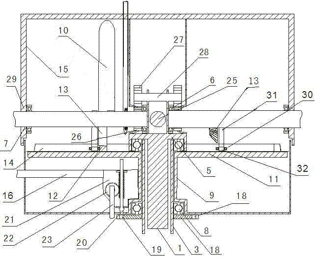
[0023] The present invention includes a main rotating shaft 1, blades 2-1, 2-2, 2-3, 2-4, a fixed shaft 3, a machine base 4, a support plate 5, a bearing 6, a leaf rotating shaft 7, 25, a bearing 8, a sleeve Cylinder 9, flat blade 10, locking disc 11, blade arc section 12, bevel gear 13, arc-shaped protruding locking blade rail 14, rotating drum 15, wind rudder 16, fixed disc 18, pin hole 19, gear rail Pin 20, bracket 21, gear 22, swing lever 23, wind direction block 24, first gear 26, second gear 27, drive shaft 28, through hole 29, lock leaf bearing 30, lock leaf shaft 31, lower arm 32, upper arm 33.
[0024] Such as figure 1 , figure 2 , image 3 and Figure 9 The present embodiment 1 shown includes a main shaft 1, blades 2-1, 2-2, 2-3, 2-4, a fixed shaft 3 and a base 4, and the fixed shaft 3 is sleeved outside the main shaft 1 , the upper part of th...
PUM
| Property | Measurement | Unit |
|---|---|---|
| Central angle | aaaaa | aaaaa |
Abstract
Description
Claims
Application Information
 - R&D
- Intellectual Property
- Life Sciences
- Materials
- Tech Scout
- Unparalleled Data Quality
- Higher Quality Content
- 60% Fewer Hallucinations
Browse by: Latest US Patents, China's latest patents, Technical Efficacy Thesaurus, Application Domain, Technology Topic, Popular Technical Reports.
© 2025 PatSnap. All rights reserved.Legal|Privacy policy|Modern Slavery Act Transparency Statement|Sitemap|About US| Contact US: help@patsnap.com