Air bearing, air floatation movement system, and method for stabilizing revolving shaft in air bearing

An air bearing and rotating shaft technology is applied in the design field of moving parts in an ultra-precision air-floating motion system, which can solve the problems of inaccurate observation, failure of observation, and inability to satisfy the static stability of air bearings, and achieve good results.

Inactive Publication Date: 2011-11-23
MICROFOCUS TECH
View PDF4 Cites 20 Cited by
  • Summary
  • Abstract
  • Description
  • Claims
  • Application Information

AI Technical Summary

Problems solved by technology

At this time, due to the pressure change between the rotating shaft and the air film, the magnetic flux change of the permanent magnet motor and other factors further affect the static stability of the air bearing, the static stability of the existing air bearing cannot meet the requirements of some applications. Require
For example, the stage containing the air bearing in the microscope needs to be fixed at a specific position for observation. At this time, the air bearing needs to be in a static state, but if the static stability of the air bearing used is poor, it will cause observation failure or inaccurate observation. ; Another example is that the workbench containing air bearings such as lithography machines or ultra-precision tool processing needs to be fixed at a specific position for continuous operation. Similarly, if the static stability of the air bearings is poor at this time, it will make the product. Yield drop

Method used


Image

  • Air bearing, air floatation movement system, and method for stabilizing revolving shaft in air bearing
  • Air bearing, air floatation movement system, and method for stabilizing revolving shaft in air bearing
  • Air bearing, air floatation movement system, and method for stabilizing revolving shaft in air bearing

Examples


Embodiment Construction

[0030] In order to make the above objects, features and advantages of the present invention more comprehensible, the present invention will be further described in detail below in conjunction with the accompanying drawings and specific embodiments.

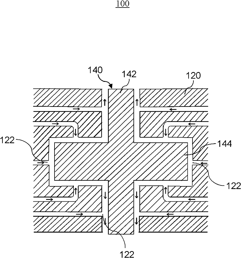
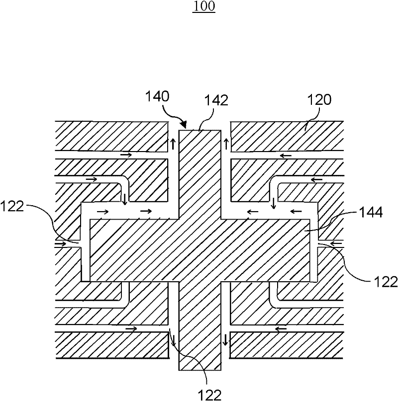
[0031] Please refer to figure 1 , which shows a schematic cross-sectional view of an air bearing in an embodiment 100 of the present invention. The air bearing 100 includes an air bearing body 120 and a rotating shaft 140 inside the air bearing body 120 .

[0032] The rotating shaft 140 includes a cylindrical rotating shaft portion 142 and a flange portion 144 formed perpendicular to the axis of the rotating shaft, the flange portion 144 is located in the middle of the cylindrical rotating shaft portion 142, and the The shape of the section of the flange portion 144 on the section including the axis of the rotating shaft (that is, the section shown in this figure) is rectangular. Several air guide holes 122 are formed on the air...


PUM


Abstract

The invention discloses an air bearing. The air bearing comprises an air bearing body and a revolving shaft which is positioned in the air bearing body; the revolving shaft comprises a revolving shaft part which is cylindrical and a flange part which is formed vertically to an axial line where the revolving shaft is; the air bearing body is provided with a plurality of air guide holes; when the revolving shaft moves, air flowing through the air guide holes forms an air membrane between the revolving shaft and the air bearing body; and when the revolving shaft is static, the axial action force provided by the air flowing through the air guide holes ensures that the partial surface of the flange part is closely contacted with the air bearing body. In the air bearing, when the revolving shaft is static, the revolving shaft is closely contacted with the air bearing body by using air, so that the revolving shaft is in a very stable state. Then, a good effect can be achieved for observation operation or other processing operation.

Description

【Technical field】 [0001] The invention relates to an air bearing, in particular to the design of moving parts used in an ultra-precision air suspension motion system. 【Background technique】 [0002] Air Bearing is one of the key components in the ultra-precision air bearing motion system contained in equipment such as microscopes, photolithography machines, and ultra-precision cutting machines. Since the air bearing uses an air film as a lubricant, it has many advantages such as high stiffness, cleanliness, and frictionlessness, but it also has the disadvantage of poor stability in certain application environments. The stability of the air bearing includes static stability and dynamic stability when the internal rotating shaft rotates at high speed. [0003] Common factors that restrict the static stability of air bearings include air hammer oscillation, micro-vibrations generated on air bearings when gas flows, self-excited resonance of air bearings, and extrusion film eff...

Claims


Application Information

Patent Timeline
Patent Type & Authority Applications(China)
IPC IPC(8): F16C32/06F16C33/00F16C41/00
CPCF16C32/06F16C33/00F16C32/0622F16C32/0696F16C41/00
Inventor 何继中
Owner MICROFOCUS TECH
Why Eureka
Try Eureka