High-brightness excitation method and light emitting device based on optical wavelength conversion

一种光波长转换、发光装置的技术,应用在光源领域,能够解决效率降低、成本高、光能损耗严重等问题,达到提高光功率密度、解决散热问题、结构简单的效果

Active Publication Date: 2011-11-23
APPOTRONICS CORP LTD
View PDF5 Cites 34 Cited by
  • Summary
  • Abstract
  • Description
  • Claims
  • Application Information

AI Technical Summary

Problems solved by technology

Its disadvantage is that because the reflectivity of the inner surface of the cavity cannot achieve the ideal 100% reflectivity, the light energy will be seriously lost after multiple reflections, resulting in a sharp decrease in efficiency
Therefore, the efficiency of this scheme to provide high-power output light is restricted
[0004] Moreover, the existing technology only considers providing excitation light from one side of the phosphor, and extracting the excited light from the other side of the phosphor, resulting in low optical power per unit area of ​​the excitation light.
[0005] In the prior art, there is a method of using a motor to drive the light wavelength conversion material to rotate and receive the irradiation of external excitation light to produce a colorful light source. However, the process and device structure are complicated and the cost is high.

Method used


Image

  • High-brightness excitation method and light emitting device based on optical wavelength conversion
  • High-brightness excitation method and light emitting device based on optical wavelength conversion
  • High-brightness excitation method and light emitting device based on optical wavelength conversion

Examples


Embodiment Construction
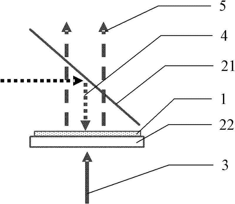
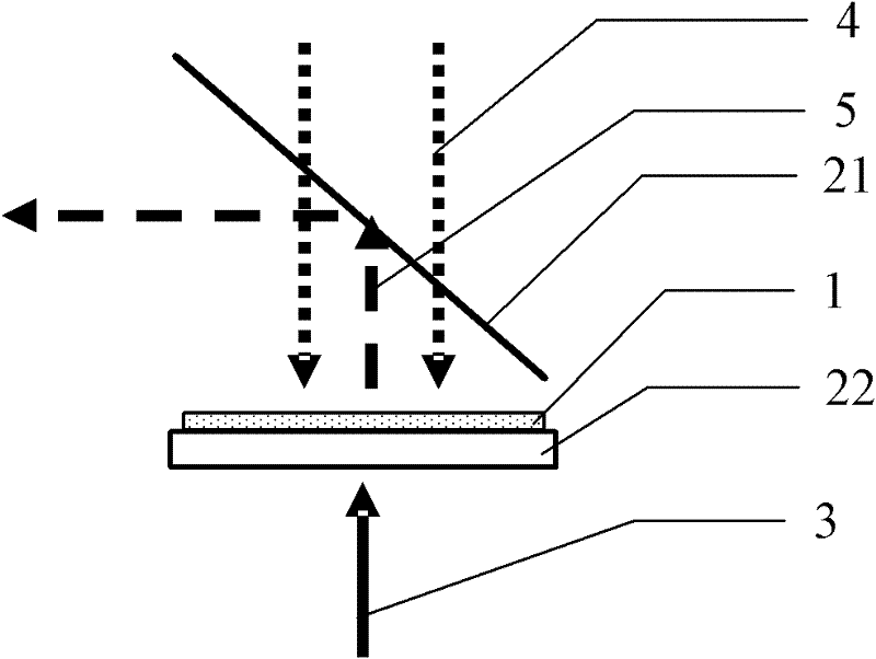
[0077] The general idea of ​​the technical scheme of the present invention is: compared with the prior art, only the excitation light is provided from one side of the phosphor powder, and the excited light is extracted from the other side of the phosphor powder; the present invention simultaneously excites the phosphor powder from both sides To increase the optical power density of the excitation light, that is, the optical power per unit area; at the same time, the problem of heat dissipation of the phosphor can be solved by measures such as a transparent heat-conducting substrate.

[0078] The technical solution for realizing the purpose of the invention will be described in detail below in conjunction with the accompanying drawings and embodiments. It should be understood that the specific embodiments described here are only used to explain the present invention, not to limit the present invention.

[0079] Please refer to figure 2 , a light-emitting device based on light...


PUM


Abstract

The invention relates to a high-brightness excitation method and a light emitting device based on optical wavelength conversion. The method comprises the following steps: two surfaces of lamellar-distributed optical wavelength conversion materials respectively receive the excitation of first excitation light and second excitation light at two sides of the optical wavelength conversion materials, and excited light is generated; the first excitation light is the excitation light which is emitted by a solid light emitting chip array which is composed of a solid light emitting chip or a pluralityof solid light emitting chips; the second excitation light is guided by a first light splitting and filtering device which is positioned at the other side of the optical wavelength conversion materials and is emitted in the optical wavelength conversion materials; and the excited light is guided by the first light splitting and filtering device and is split into outgoing light from the light pathof the second excitation light. The two surfaces of the optical conversion materials are excited simultaneously, the excitation light and the excited light are guided by adopting the corresponding light splitting and filtering device, the heat radiation issue is solved through tightly clinging a transparent heat conduction substrate or an LED (light emitting diode) chip to the optical wavelength conversion materials, and the high-brightness high-power light output of the light emitting device is realized.

Description

technical field [0001] The invention relates to the field of light source technology, in particular to a high-brightness excitation method and a light-emitting device based on light wavelength conversion. Background technique [0002] In order to obtain an illumination source with rich colors, high brightness and low cost, the prior art usually uses a light source to excite a light wavelength conversion material such as a phosphor to generate stimulated light. [0003] In the prior art, in order to increase the brightness of the output light, it is usually preferred to improve the excitation or extraction efficiency of the light conversion material. Taking phosphor as an example, in order to make the phosphor have a higher extraction efficiency, the phosphor is placed in a reflective space In the cavity, an excitation light source is set on the inner surface of the cavity, and at the same time, it is emphasized that the exit area of ​​the cavity is smaller than the area of ​...

Claims


Application Information

Patent Timeline
Patent Type & Authority Applications(China)
IPC IPC(8): F21K99/00F21V9/10F21V17/00F21V19/00F21V9/40
CPCH04N9/3161F21Y2101/02F21V9/16F21Y2105/001H04N9/315F21Y2105/10F21Y2115/10F21V9/30F21V13/08F21V9/45
Inventor 李屹杨毅
Owner APPOTRONICS CORP LTD
Why Eureka
Try Eureka