Cam contour detecting system based on direct drive motor

A direct-drive motor and detection system technology, applied in the direction of measuring devices, instruments, optical devices, etc., can solve the problems of not being able to adapt to the production of cam automatic lines, and achieve the effect of good dynamic performance, fast speed and high precision of the system

Active Publication Date: 2012-11-28
江苏今越控股集团有限公司
View PDF0 Cites 0 Cited by
  • Summary
  • Abstract
  • Description
  • Claims
  • Application Information

AI Technical Summary

Problems solved by technology

To achieve high-precision and high-efficiency detection of cams, correct processing and evaluation of its errors, and timely and rapid feedback of cam quality information, traditional optical-mechanical measuring instruments and manual data processing methods can no longer adapt to the wide range of cams. The need for automatic line production

Method used


Image

  • Cam contour detecting system based on direct drive motor
  • Cam contour detecting system based on direct drive motor
  • Cam contour detecting system based on direct drive motor

Examples


Embodiment 1

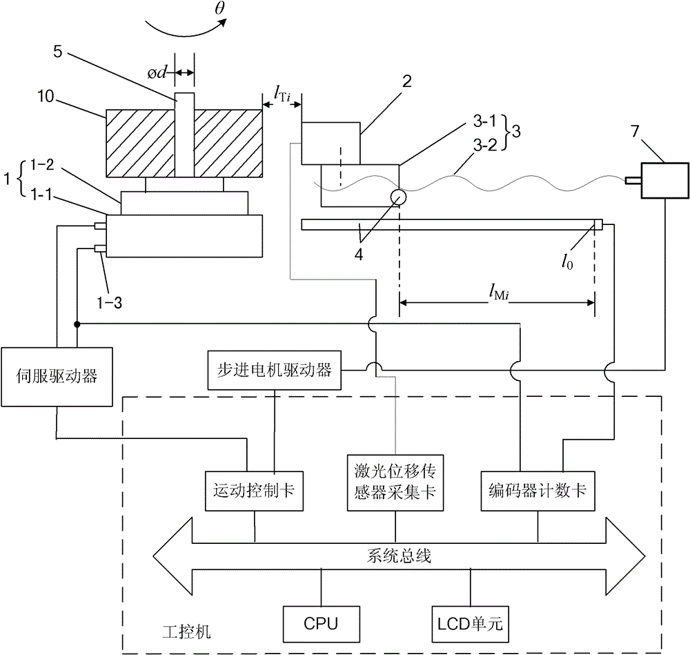
[0022] See Figure 1-2 The cam profile detection system based on the direct-drive motor in this embodiment includes: a direct-drive motor 1 for driving the cam 10 to rotate horizontally and coaxially around the vertical mandrel 5; The screw nut pair 3, the laser measuring head 2 arranged on the movable nut 3-1 of the screw nut pair 3 and on the side of the cam 10, the grating for measuring the horizontal displacement of the movable nut 3-1 A ruler displacement sensor 4, a circular grating for detecting the rotation angle of the cam 10 provided in the fixed seat 1-1 of the direct-drive motor 1, and an industrial computer; the industrial computer controls the direct-drive motor 1 and the wire The rod nut pair 3 moves, and the outer contour data of the cam 10 is obtained according to the data measured by the laser measuring head 2, the grating scale displacement sensor 4 and the circular grating. The motion control card is connected with the direct-drive motor 1 through a servo ...

Embodiment 2

[0046] On the basis of Embodiment 1, this embodiment has the following modifications:

[0047] In order to eliminate the influence of the machining or installation error of the mandrel 5 on the detection accuracy of the cam profile, the detection method of the cam profile detection system includes:

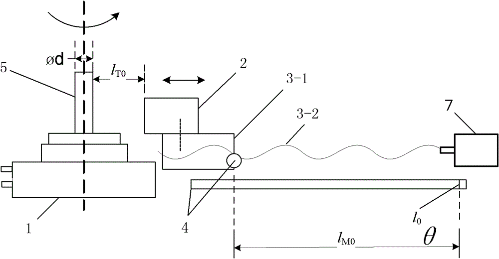
[0048] A. Detect the data of the outer edge of the mandrel 5: when the mandrel 5 starts to rotate for one cycle, the distance between the laser measuring head 2 and the outer circle of the mandrel 5 is the first distance l T0i It is always controlled within the range of the laser measuring head 2, and at the same time, it is detected and recorded with the rotation angle as θ i The corresponding first distance l T0i , and the mover 3-1 is in the horizontal direction with the hard zero position 1 0 The spacing is the second spacing l M0i ;

[0049] B. Fit the cam 10 on the mandrel 5 without clearance. If the outer contour data of the cam 10 is known, ρ=ρ(θ), the laser measuring ...


PUM


Abstract

The invention provides a cam contour detecting system based on a direct drive motor. The cam contour detecting system has the advantages of simple structure, high detection accuracy and higher efficiency and comprises a direct drive motor, a mandrel coaxially and fixedly arranged on a rotor of the direct drive motor and used for driving a cam to rotate synchronously and coaxially, a screwpair horizontally arranged at one side of the cam, a laser measuring head on a traveling nut of the screwpair, a grating ruler displacement sensor for measuring the horizontal displacement of the traveling nut, a circular grating arranged in the direct drive motor fixing seat and used for detecting the rotational angle of the rotor and an industrial control computer; and the industrial control computer isused for controlling the direct drive motor and the screwpair to act, and obtaining the outer contour data of the cam, according to the data measured by the laser measuring head, the grating ruler displacement sensor and the circular grating.

Description

technical field [0001] The invention relates to a cam profile detection system based on a direct-drive motor and a detection method thereof. Background technique [0002] Cam mechanisms are widely used in various automated machinery, precision instruments, automated control systems, etc. In order to detect the cam with high precision and high efficiency, correctly handle and evaluate its various errors, and feed back the quality information of the cam in a timely and rapid manner, the traditional optical mechanical measuring instrument and manual data processing methods can no longer adapt to the wide range of cams. The use of automatic line production is required. With the rapid development of the automobile industry, construction machinery, etc. and the continuous improvement of manufacturing technology, how to improve the detection accuracy and efficiency of the cam machining accuracy is a technical problem to be solved in this field. SUMMARY OF THE INVENTION [0003]...

Claims


Application Information

Patent Timeline
Patent Type & Authority Patents(China)
IPC IPC(8): G01B11/24
Inventor 丁仕燕
Owner 江苏今越控股集团有限公司
Why Eureka
Try Eureka