
Optical fiber compound sensing module

A sensing module and optical fiber composite technology, which is applied in the direction of using optical devices to transmit sensing components, can solve the problems of affecting the realization of the device, large gripping force, difficult to realize, etc., and achieves convenient implementation, simple base material, and consistent deformation. Effect

Active Publication Date: 2011-11-23
CHONGQING UNIV
View PDF4 Cites 5 Cited by
  • Summary
  • Abstract
  • Description
  • Claims
  • Application Information

AI Technical Summary

Problems solved by technology

It needs to be equipped with light source, spectrometer (or spectrometer) and OTDR and other equipment at the same time, which is difficult and inconvenient in practical applications; moreover, the grouting materials between the module and the borehole, such as cement mortar, concrete, etc., are harmful to the device itself. The grip force is very large, which will seriously affect the realization of the intended function of the device

Method used


Image

  • Optical fiber compound sensing module
  • Optical fiber compound sensing module
  • Optical fiber compound sensing module

Examples

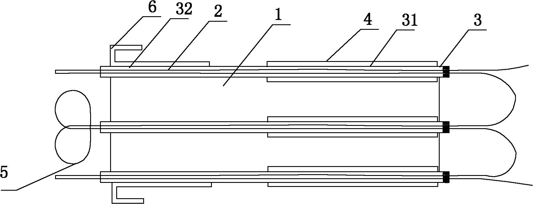
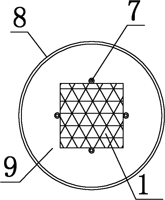

Embodiment Construction

[0025] Hereinafter, preferred embodiments of the present invention will be described in detail with reference to the accompanying drawings. It should be understood that the preferred embodiments are only for illustrating the present invention, but not for limiting the protection scope of the present invention.

[0026] see figure 1 , the optical fiber composite sensing module of this embodiment includes a base material 1, the shape and size of the base material 1 can be selected according to needs, the cross section of the base material 1 of this embodiment is a square, and the material of the base material can be selected according to The material parameters of the tested body are selected. The expanded polyester vinyl has a large plasticity and is relatively soft, which is suitable for the situation where the measured body is relatively loose and the strength is not high, or PVC needs to be assembled on site, and the strength and rigidity are relatively high. Large, suitabl...


PUM


Abstract

The invention relates to the technical field of realizing synchronous measurement of deformation and direction of motion by adopting an optical fiber device, and in particular relates to a composite optical fiber detection module which is simple and convenient to apply, and simultaneously eliminates the bond stress influence of a grouting material on optical fibers. According to the technical scheme disclosed by the invention, the optical fiber compound sensing module comprises a base material, wherein the surface of the base material is provided with the optical fibers; a sleeve I is sleevedon the optical fibers; the sleeve I comprises a free section and an anchoring section which is anchored on the base material; a sleeve II is arranged outside the sleeve I at the free section; and thesleeve I at the anchoring section is provided with the anchoring block which is used for anchoring. According to the invention, one optical fiber is arranged on each surface of the base material, high initial measuring accuracy, large measuring stroke and dynamic range and the judgment of load direction can be realized, additionally the free motion of the optical fibers can be ensured without theinfluence by the bond stress of the grouting material, and the deformation of measured objects and other information can be monitored synchronously.

Description

technical field [0001] The invention relates to the technical field of using an optical fiber device to realize synchronous measurement of deformation and motion direction, in particular to an optical fiber composite sensing module. Background technique [0002] The earth is the place we live on, and our environment is closely related to our life. The land area accounts for less than 30% of the earth's surface area, of which mountains, plateaus, and hills account for the vast majority of the earth's surface area, and a lot of slopes have been formed during the geological tectonic movement; and with the continuous expansion of human activities, There will also be many slopes formed by manual excavation or filling. However, the most critical thing is that the hazards of unstable slopes are almost everywhere due to global warming, land overuse, overpopulation, harsh climate, earthquakes, and deteriorating environment. [0003] my country has a vast territory, 70% of which is ...

Claims


Application Information

Patent Timeline
IPC IPC(8): G01D5/26
Inventor 朱正伟袁侨英刘东燕刘邦罗虎
Owner CHONGQING UNIV
Learn More