Assembly of semiconductor power modules

a technology of power modules and semiconductors, applied in the direction of process and machine control, semiconductor/solid-state device details, instruments, etc., to achieve the effects of facilitating connection, reducing noise, and reducing heat dissipation

Pending Publication Date: 2022-04-28
COMMISSARIAT A LENERGIE ATOMIQUE ET AUX ENERGIES ALTERNATIVES
View PDF0 Cites 0 Cited by
  • Summary
  • Abstract
  • Description
  • Claims
  • Application Information

AI Technical Summary

Benefits of technology

[0022]The assembly also has a modular configuration which readily allows the number of superposed modules to be increased or decreased depending on the number of phases of the equipment used or on the current requirements.
[0025]The invention allows the imbalance between the controls of the various modules to be limited owing to the different lengths of conductors, and thus the noise to be limited. The fact that the connections to the driver circuit may be made on the same side for all the modules of the assembly facilitates the connection in parallel of the modules or the multi-phase.
[0026]The substrate can contribute to the heat dissipation by being advantageously made from a material with a good thermal conductivity, such as a ceramic.
[0029]Preferably, for each power module, the first connection element electrically connects together the first power contact of the first component (for example the Source) and the first power contact of the second component (for example the Drain), outside of the substrate. This may contribute to simplifying the substrate, which does not have to integrate power electrical tracks, and allows a material with a good thermal conductivity such as a ceramic to be used to form the substrate.
[0034]Each component may comprise at least one control contact (for example a Gate contact), each module comprising at least two output terminals, notably output terminals defined by connectors carried by the module, in order to electrically connect the control contacts of the power components to a driver circuit. All the output terminals, notably all the connectors, are advantageously situated on the same side of the module, and all the connectors are preferably situated on the same side of the assembly of modules. This allows the asymmetries in the control of the components to be limited by matching the lengths of the control conductors, the noise together with the stray inductances in the control to be reduced, and can facilitate the installation of a driver card near to the assembly of modules.
[0064]In contrast, the channels situated on one face and receiving the conductors connected to the control connector of a component present on this face are preferably laterally offset with respect to the channels present on the other face and used to control the power component present on this other face, in such a manner as to facilitate the installation of the connectors.

Problems solved by technology

Such an assembly of modules represents a compact arrangement which cannot be efficiently cooled.

Method used


Image

  • Assembly of semiconductor power modules
  • Assembly of semiconductor power modules
  • Assembly of semiconductor power modules

Examples


Embodiment Construction

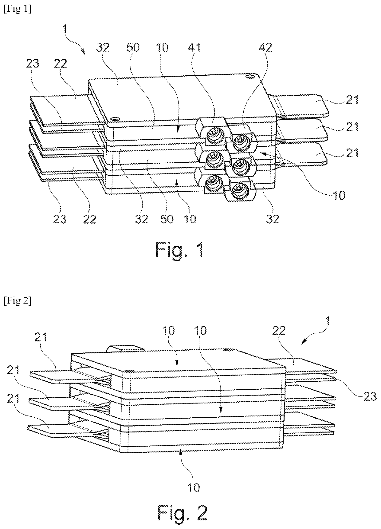
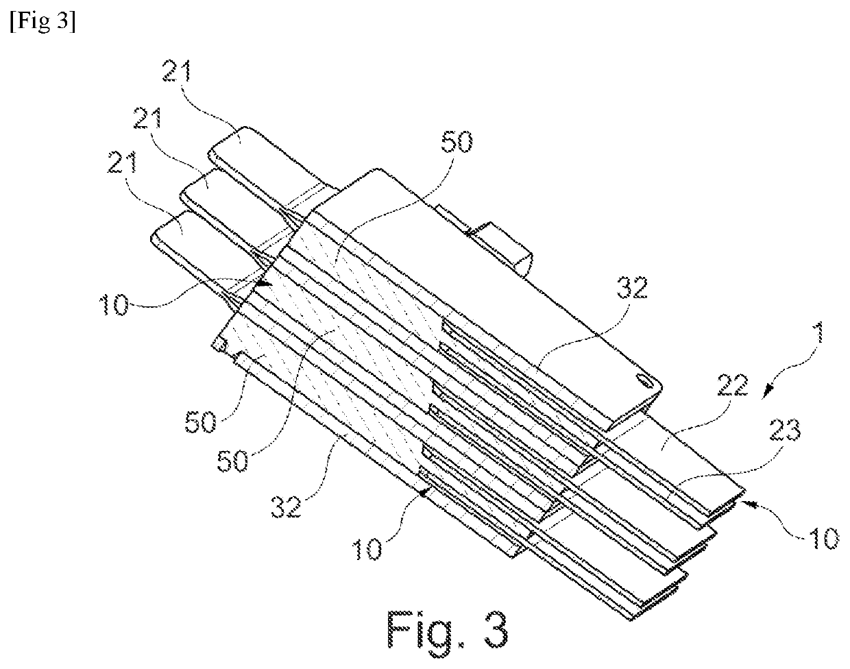
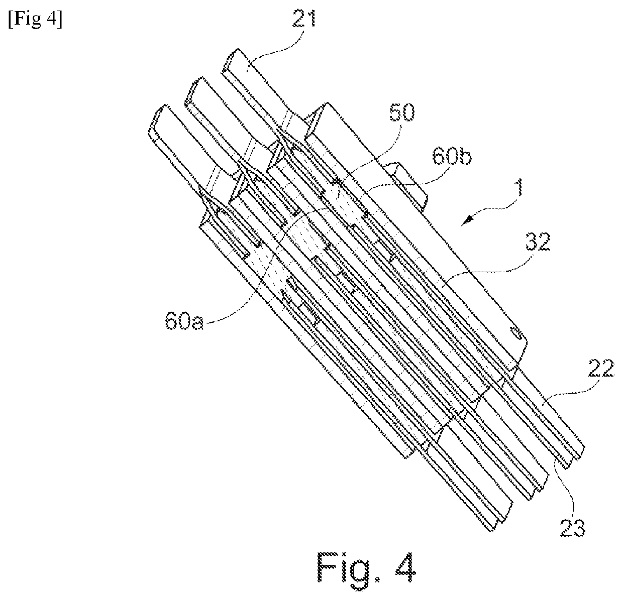
[0010]Equipment supplied by the power modules usually has several phases or is controlled by modules configured in parallel, and there exists a need for an assembly of multi-phase modules or modules connected in parallel, which are both compact and optimized with respect to the heat dissipation, while at the same time minimizing the stray inductances.

SUMMARY OF THE INVENTION

[0011]The invention aims to meet this need, and it achieves this, according to a first of its aspects, by providing an assembly of power modules, comprising at least two superposed power modules, each power module comprising:[0012]An electrically insulating substrate, having opposing main faces,[0013]at least a first and a second semiconductor component, disposed one on top of the other on either side of the substrate and resting on its main faces, each component having at least two power contacts,[0014]a first connection element electrically connected to a first power contact of the first component and to a firs...


PUM


Abstract

Assembly of power modules (10), each power module comprising:at least a first (60a) and a second (60b) component disposed one on top of the other on either side of the substrate, each component having at least two power contacts,a first connection element (21) electrically connected to a first power contact of the first component and to a first power contact of the second component,a second connection element (22) electrically connected to a second power contact of the first component,a third connection element (23) electrically connected to a second power contact of the second component,the first connection elements of the modules being disposed on the same side of the assembly,the second connection elements of the modules being disposed on the same side of the assembly,the third connection elements of the modules being disposed on the same side of the assembly.

Description

[0001]The present invention relates to semiconductor power modules, such as those used for switching high currents.PRIOR ART[0002]Certain power modules comprise two transistors associated according to a half-bridge configuration, with terminals to be connected to a DC bus and an output corresponding to one phase, intended to be connected to equipment such as an electrical rotating machine for example. A decoupling capacitor is connected between the terminals of the DC bus. Terminals are also provided for the connection to a control or ‘driver’ circuit for the transistors.[0003]Depending on the number of phases of the equipment to be powered or of the power to be switched, several power modules may be used, which are connected in parallel in this case.[0004]The development of transistors based on Gallium Nitride has allowed the operating frequencies to be increased, which renders the stray inductances associated with connections within the module critical.[0005]Today, the majority of...

Claims


Application Information

Patent Timeline
Patent Type & Authority Applications(United States)
IPC IPC(8): H02M3/00H02M3/158H05K7/20
CPCH02M3/003H05K7/209H02M3/158H01L25/117H01L25/18H01L25/072H01L23/467H05K7/14329
Inventor MARCAULT, EMMANUELSOULIE, SARAH
Owner COMMISSARIAT A LENERGIE ATOMIQUE ET AUX ENERGIES ALTERNATIVES
Why Eureka
Try Eureka