System and method for surface plasmon resonance sensing detection

A surface plasma and detection system technology, applied in the field of photoelectric detection, can solve problems such as poor stability, achieve good stability, and improve detection speed and accuracy.

Inactive Publication Date: 2011-11-23
SHENZHEN UNIV +2
View PDF4 Cites 21 Cited by
  • Summary
  • Abstract
  • Description
  • Claims
  • Application Information

AI Technical Summary

Problems solved by technology

[0003] The purpose of the embodiments of the present invention is to provide a surface plasmon resonance intensity detection system, which aims to solve the problem that the existing surface plasmon resonance intensity detection system needs to use a mechanical scanning device to modulate the angle of the light source and has poor stability.

Method used


Image

  • System and method for surface plasmon resonance sensing detection
  • System and method for surface plasmon resonance sensing detection
  • System and method for surface plasmon resonance sensing detection

Examples


Embodiment 1

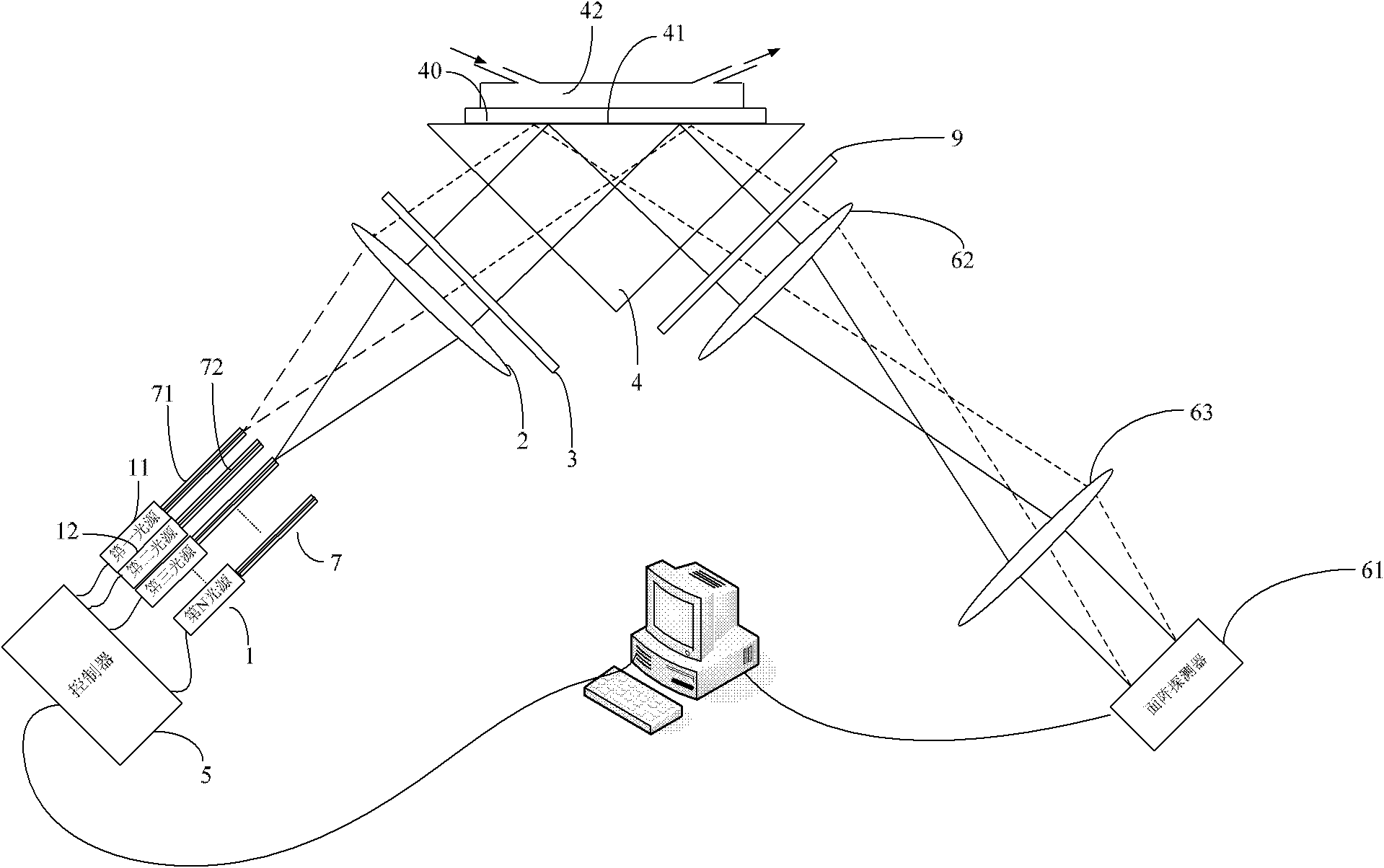
[0033] figure 1 The structure of the surface plasmon resonance sensing detection system provided by the embodiment of the present invention is shown, and for the convenience of description, only the parts related to the embodiment of the present invention are shown. The surface plasmon resonance sensing detection system includes a light source 1, a first lens 2, a polarizer 3, a prism 4, a controller 5 and an imaging mechanism.

[0034] In the embodiment of the present invention, the light source 1 first generates sensing light, wherein the sensing light is preferably a narrow-band laser, and is generally generated by a laser as a light source. There are multiple light sources, and in order to output each sensing light to the focal plane of the first lens, the narrow-band laser light generated by each light source is transmitted by the optical fiber 7, so there are multiple optical fibers, and the multiple optical fibers form a dense optical fiber array. The narrow-band laser...

Embodiment 2

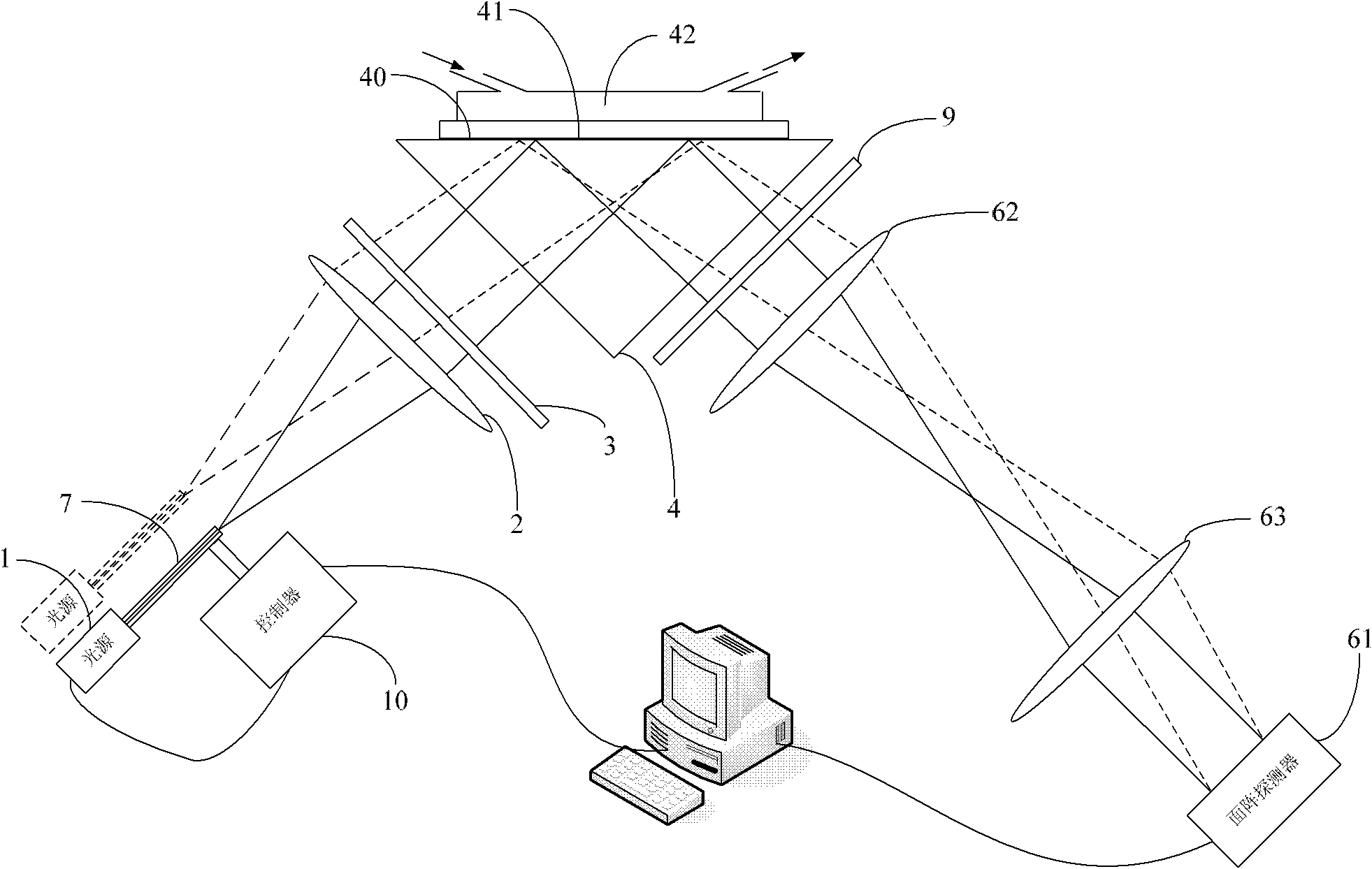
[0042] figure 2 The structure of the surface plasmon resonance sensing detection system provided by the embodiment of the present invention is shown, and for the convenience of description, only the parts related to the embodiment of the present invention are shown.

[0043] In the embodiment of the present invention, the multiple light sources in the first embodiment are replaced by scanning the section of the optical fiber, that is, the controller 10 controls the optical fiber 7 to scan one step, the light source 1 lights up once, and the imaging mechanism generates an image, which is equivalent to switching to different light sources. In this way, only one light source is needed to complete the SPR angle scanning, which greatly reduces the cost.

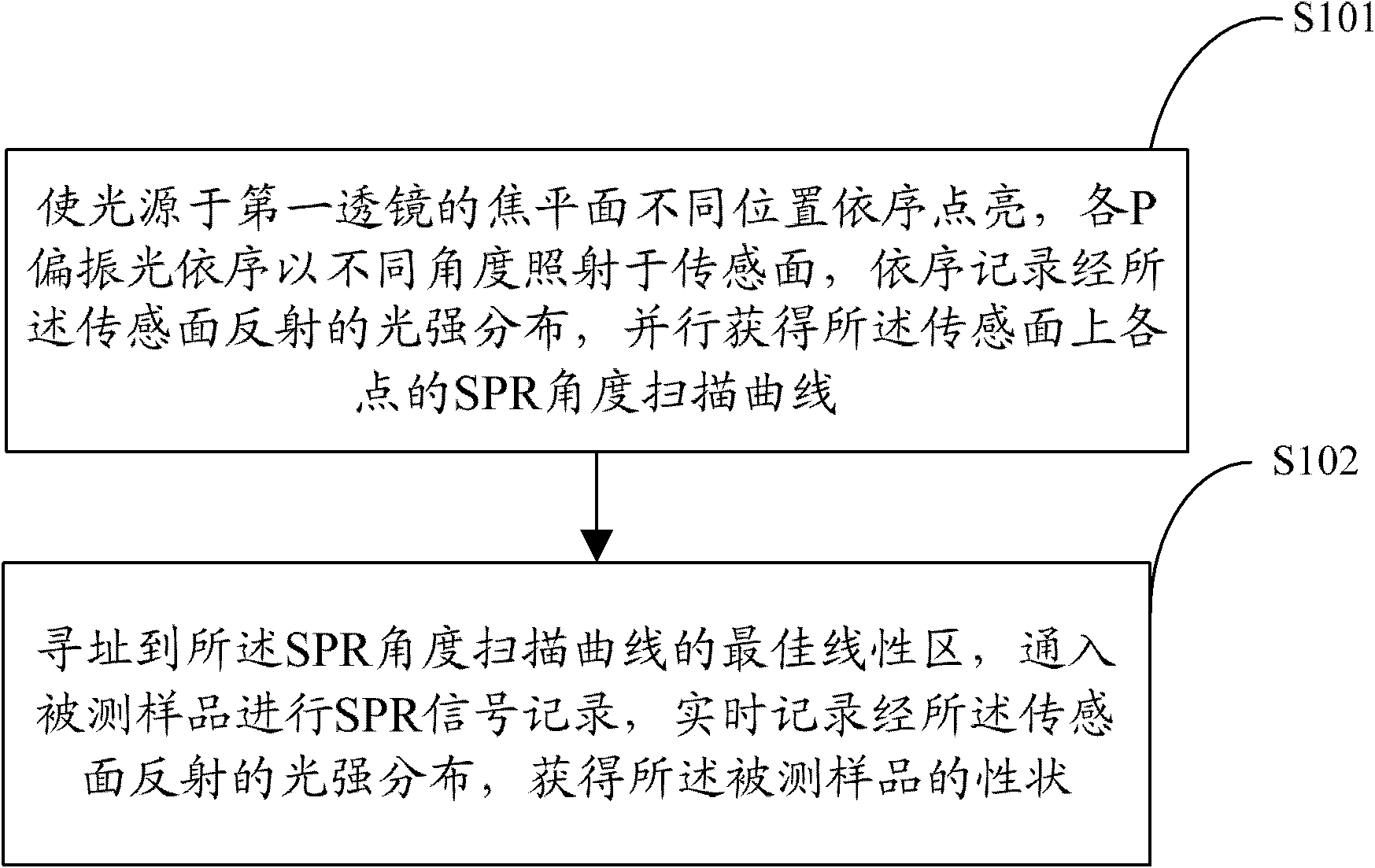
[0044] image 3 The implementation flow of the surface plasmon resonance sensing detection method provided by the embodiment of the present invention is shown. For the convenience of description, only the parts related to the e...


PUM


Abstract

The invention which is suitable for a photoelectric detection technology provides a system and a method for surface plasmon resonance sensing detection. The system comprises: light sources for generating sensing lights; a first lens for adjusting the sensing lights into collimated lights; a polarizer for obtaining P-polarized lights in the collimated lights; a prism for receiving the P-polarized lights to irradiate the P-polarized lights onto a sensing surface; a controller for controlling the light sources to allow the light sources to be sequentially lightened at different positions of a focal plane of the first lens and sequentially irradiate each P-polarized light onto the sensing surface from different angles; and an imaging mechanism for recording the intensity distribution of lights reflected by the sensing surface. According to the invention, the light sources are sequentially lightened at different positions of the focal plane of the first lens through an electronic control mode, so the P-polarized lights are sequentially irradiated onto the sensing surface from different angles, the intensity distribution of the lights reflected by the sensing surface is recorded in real time, SPR angular scan curves of each point on the sensing surface are obtained in parallel, the stability is good, and the speed is fast.

Description

technical field [0001] The invention belongs to photoelectric detection technology, in particular to a surface plasmon resonance sensing detection system and method. Background technique [0002] Surface plasmon resonance (Surface Plasmon Resonance, SPR) is an emerging sensing technology, which has the advantages of high sensitivity, high throughput, easy to achieve specific detection and real-time, and does not require labeling, etc., and has been widely used in biological , medicine, food quality and safety, chemical and environmental monitoring and other industries, especially for online real-time detection of biomolecules such as DNA and protein, protein molecules, and drug-protein, nucleic acid-nucleic acid, antigen-antibody, receptor-ligand, etc. interactions between them, etc. However, the current SPR sensing technology requires a mechanical scanning device to modulate the angle of the light source, which has poor stability and low precision. Contents of the invent...

Claims


Application Information

Patent Timeline
Patent Type & Authority Applications(China)
IPC IPC(8): G01N21/63
Inventor 邵永红顾大勇屈军乐庄卫东史蕾刘春晓赵纯中杨燕秋徐云庆季明辉欧青叶孙秋香徐华
Owner SHENZHEN UNIV
Why Eureka
Try Eureka