Microwave nondestructive testing device of metal surface defects and testing method thereof

A metal surface, non-destructive testing technology, applied in the use of microwave flaw detection and other directions, can solve the problems of inability to real-time online monitoring, low detection rate of metal surface defects, inability to record, analyze, process and archive inspection results, and achieve automation. The effect of detection

Inactive Publication Date: 2011-11-23
TAIYUAN UNIV OF TECH
View PDF3 Cites 20 Cited by
  • Summary
  • Abstract
  • Description
  • Claims
  • Application Information

AI Technical Summary

Problems solved by technology

The frequency of the eddy current detector is low, the penetration is poor, and the detection rate of metal surface defects under the non-metallic coating is low, or even undetectable
In addition, when testing, the metal surface must be tested without external interference, real-time online monitoring is not possible, and the test results cannot be recorded, analyzed, processed and archived.

Method used


Image

  • Microwave nondestructive testing device of metal surface defects and testing method thereof
  • Microwave nondestructive testing device of metal surface defects and testing method thereof
  • Microwave nondestructive testing device of metal surface defects and testing method thereof

Examples


specific Embodiment approach 1

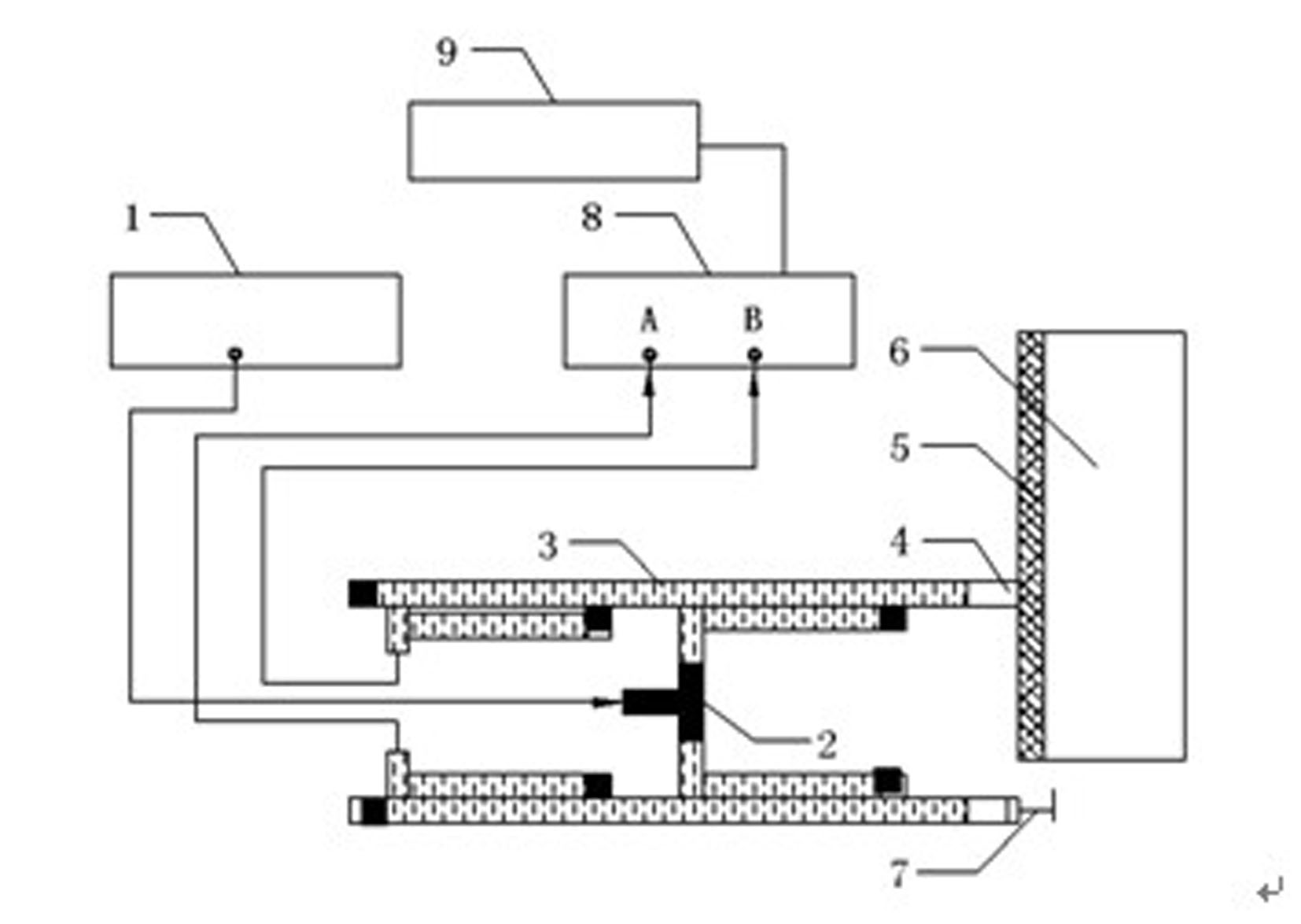
[0019] Implementing a microwave non-destructive detection device for metal surface defects described in the present invention includes setting a "T"-shaped tube 2 through a waveguide-coaxial converter and a coaxial line connected to a microwave frequency scanner 1, wherein:

[0020] The structure of the "T"-shaped pipe 2 includes a long arm and a cross arm, and the middle part of the cross arm is vertically integrated with the long arm and communicates with the long arm. In the present invention, the "T" type tube 2 is a "T" type microwave channel tube structure in which the main waveguide is perpendicular to the first waveguide and the second waveguide, and the first waveguide and the second waveguide are respectively coupled with the directional The corresponding input signal of the device 3 is transmitted. When the main waveguide receives the signal, the two arms of the first waveguide and the second waveguide excite microwave signals of equal amplitude and phase.

[0021] ...

specific Embodiment approach 2

[0024] Implement the detection method of a kind of metal surface defect microwave nondestructive detection device described in the present invention:

[0025] Such as figure 1 , a detection method for the metal surface defect microwave non-destructive detection device according to the present invention, the detection method is to feed the frequency-sweeping microwave signal generated by the microwave frequency sweeper 1 into a "T"-shaped tube, "T" The microwave input signal is then divided into the first signal and the second signal with the same size and phase by the type tube, which are respectively fed to the corresponding input ends of the directional coupler 3. When the main waveguide receives the signal, the two arms of the first waveguide and the second waveguide A microwave signal of equal amplitude and phase is excited; wherein, the first waveguide signal is fed to the rectangular waveguide with the first terminal opening, and the waveguide terminal opening is provide...


PUM


Abstract

The invention provides a microwave nondestructive testing device of metal surface defects and a testing method thereof. The device is characterized in that a T-shaped tube is in signal connection with a microwave frequency scanning meter via a waveguide-coaxial transducer; a first waveguide and a second waveguide of the T-shaped tube are respectively connected with input ends corresponding to a directional coupler; when a main waveguide receives signals, the two arms of the first waveguide and the second waveguide trigger equal-amplitude and cophase microwave signals; the directional coupler is provided with a waveguide probe and a short-circuiting piston at a first port and a second port; the corresponding end of the waveguide probe is connected to a testing end B of a microwave vector network analyzer via the waveguide-coaxial transducer; and the corresponding end of the short-circuiting piston is connected to a testing end A of the microwave vector network analyzer via the waveguide-coaxial transducer. The method is characterized by pressing the waveguide probe vertically close to the tested metal or nonmetal surface to scan the tested metal or nonmetal surface during testing. The device and the method realize positioning and quantitative direct testing of the metal surface defects and automated testing integrating testing, recording, analyzing, processing and filing.

Description

technical field [0001] The invention relates to a metal defect detection device and a detection method thereof, in particular to a metal surface defect microwave detection device comprising a microwave frequency sweeper, a "T" tube, a directional coupler, a waveguide probe, a short-circuit piston and a microwave vector network analyzer. Non-destructive testing device and testing method thereof. Background technique [0002] Existing non-destructive testing methods for metal surface defects include penetrant method (PT), magnetic particle method (MT), eddy current method (ET), etc., but there are great limitations in some testing conditions. For example, both the infiltration method and the magnetic particle method are direct contact detection, and the detection cannot be carried out when the metal to be tested is covered or wrapped by non-metal. However, the infiltration method is difficult to determine the actual depth of the defect, and there is a problem of environmental...

Claims


Application Information

Patent Timeline
Patent Type & Authority Applications(China)
IPC IPC(8): G01N22/02
Inventor 段滋华李艳萍杨晨马海桃何银凤王世乾姚远
Owner TAIYUAN UNIV OF TECH
Why Eureka
Try Eureka