General fixing device for probe of acoustic emission detection apparatus

A technology for acoustic emission detection and fixing devices, which is applied to measuring devices, measuring instrument components, and material analysis using sound waves/ultrasonic waves/infrasonic waves. The device has the advantages of simple structure, convenient operation and strong versatility

Inactive Publication Date: 2011-11-23
BEIHANG UNIV
View PDF5 Cites 33 Cited by
  • Summary
  • Abstract
  • Description
  • Claims
  • Application Information

AI Technical Summary

Problems solved by technology

[0003] In the process of using acoustic emission probes for detection, due to the complexity of the actual working conditions, it often takes considerable time and effort to fix the acoustic emission probes effectively in many cases, and probes of different heights and diameters often need to be equipped with multiple probes. There are different types of corresponding fixing devices, which makes the on-site inspection personnel have to carry a variety of fixing devices, which brings a lot of inconvenience
For example, some existing probe fixing devices mostly use magnetic fixing, which can only be conveniently applied to the detection of ferromagnetic materials; the existing probe fixing devices are often only suitable for probes of one diameter. Either it cannot be fixed, or it cannot be firmly fixed; the existing probe fixing devices are often only suitable for fixing a specific height of the probe, and cannot achieve stable fixing for multiple probes with large height differences; Multiple probes are involved, and sometimes there will be looseness between different probes and corresponding fixtures. When looseness occurs, the coupling force between the probe and the object under test is too small, and it is often impossible to determine the occurrence of looseness from the appearance

Method used


Image

  • General fixing device for probe of acoustic emission detection apparatus
  • General fixing device for probe of acoustic emission detection apparatus
  • General fixing device for probe of acoustic emission detection apparatus

Examples


Embodiment Construction

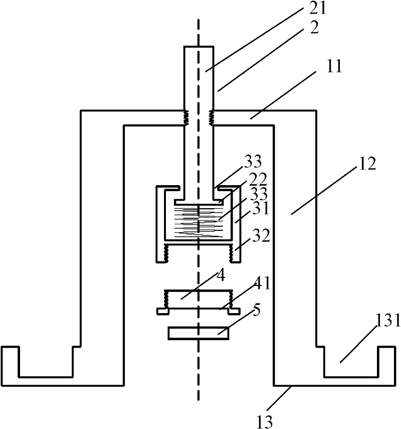
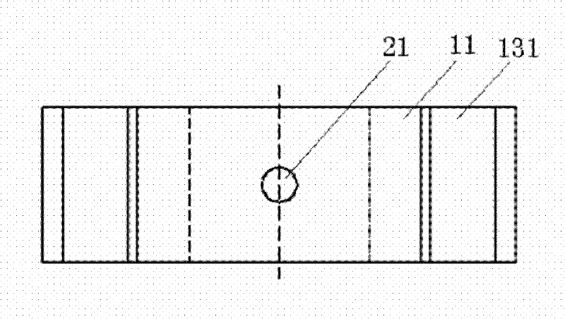
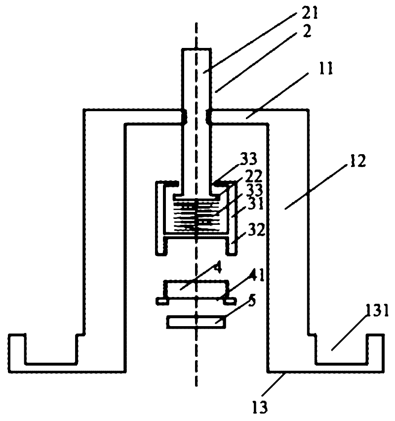
[0023] Attached Figure 1-2 The corresponding relationship between each reference number and the name of each component is: main body (1), height adjustment push rod (2), push rod pressure cap connector (3), replaceable probe pressure cap (4), probe ( 5) Cover (11), frame (12), bottom (13) of main body (1), hole (14), probe crimping surface (41), pressure sensitive sensor (42), push rod main body (21) ), the bottom end of the push rod (22), the upper cylinder connector (31), the lower connector (32), the spring (33), the opening (34), the groove (131);

[0024] in Figure 1-2 Among them, the universal fixing device includes a main body (1), a height adjustment push rod (2), a push rod pressure cap connector (3) and a replaceable probe pressure cap (4), wherein,

[0025] The main body (1) has a left-right symmetrical "ji"-shaped structure viewed from the front view direction, and the top of the "ji"-shaped structure is the cover (11) of the main body (1). The cover part (11) of (...


PUM


Abstract

The invention relates to a general fixing device for a probe of an acoustic emission detection apparatus, and particularly, relates to a general fixing device for fixing the probe. The device comprises a main body, a height-adjusting push rod, a push rod pressing cap connecting member, and a replaceable probe pressing cap, wherein the replaceable probe pressing cap has different diameters, and has a probe pressing surface which can be replaced according to the diameter of the probe; and the device further comprises a pressure display unit which is used to display a pressure signal detected by a pressure-sensitive sensor for real-time understanding of the fixing condition of the probe by detection personnel. The device of the invention has a simple and compact structure, and is convenient for carrying; the device has strong generality, and can fix according to probes with different heights and diameters; the device is convenient for operation, and is convenient for probe pressing cap replacement; the spring in the invention provides a stable pressure; therefore, even if the fixing device itself becomes loose slightly, the fixing force applied to the probe dose not change greatly, and excessively small coupling force between the probe and an object to be detected is not caused finally.

Description

Technical field [0001] The invention relates to a fixing device for a probe of an acoustic emission detection equipment, and in particular to a general fixing device for fixing the probe. Background technique [0002] The phenomenon that a local source quickly releases energy in a material to generate a transient elastic wave is called Acoustic Emission (AE). Acoustic emission is a common physical phenomenon. The frequency range of acoustic emission signals of various materials is very wide, ranging from infrasound frequencies of a few Hz, acoustic frequencies of 20Hz~20KHz to ultrasonic frequencies of several MHz; the amplitude of acoustic emission signals varies widely. Large, moving from a microscopic dislocation of 10m to a seismic wave of the magnitude of 1m. If the strain energy released by acoustic emission is large enough, it can produce audible sound. Acoustic emission occurs when most materials are deformed and fractured, but the acoustic emission signal strength of m...

Claims


Application Information

Patent Timeline
Patent Type & Authority Applications(China)
IPC IPC(8): G01N29/22G01D11/16
Inventor 张峥李丽菲
Owner BEIHANG UNIV
Why Eureka
Try Eureka