Airborne three-dimensional synthetic aperture radar imaging system based on transmitted beam scanning

A synthetic aperture radar and transmitting beam technology, applied in the radar field, can solve the problems of poor timeliness, complex imaging processing, and large amount of echo data, and achieve the effects of strong timeliness, low complexity, and small amount of received echo data.

Inactive Publication Date: 2011-11-23
XIDIAN UNIV
View PDF1 Cites 22 Cited by
  • Summary
  • Abstract
  • Description
  • Claims
  • Application Information

AI Technical Summary

Problems solved by technology

[0005] To sum up, the outstanding problems faced by the existing down-looking 3D synthetic aperture

Method used


Image

  • Airborne three-dimensional synthetic aperture radar imaging system based on transmitted beam scanning
  • Airborne three-dimensional synthetic aperture radar imaging system based on transmitted beam scanning
  • Airborne three-dimensional synthetic aperture radar imaging system based on transmitted beam scanning

Examples


Embodiment 1

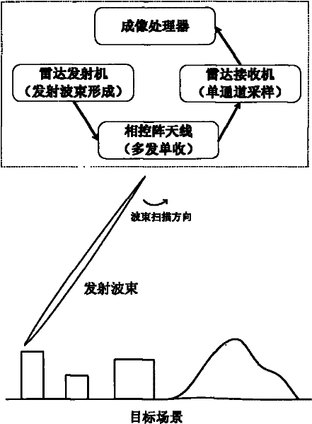
[0041] The present invention is an airborne down-looking three-dimensional synthetic aperture radar imaging system based on transmitting beam scanning, see figure 1 , the system includes: a radar transmitter, a phased array antenna, a radar receiver and an imaging processor, wherein the radar transmitter generates a beam and transmits it to each transmitting array of the phased array antenna installed in the vertical direction of the flight plane The radar echoes of the emitted beams irradiating the target scene are received one by one synchronously by the receiving elements of the phased array antenna, and sent to the radar receiver for echo data sampling, and then sent to the imaging processor To complete the imaging processing of the echo data.

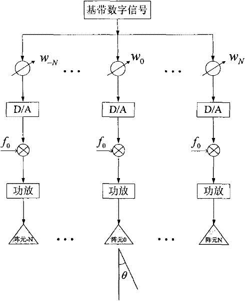
[0042] The beam generated by the radar transmitter of the present invention is a beam generated by transmitting beamforming technology, and the schematic diagram of the principle of transmitting beamforming can be found in figure...

Embodiment 2

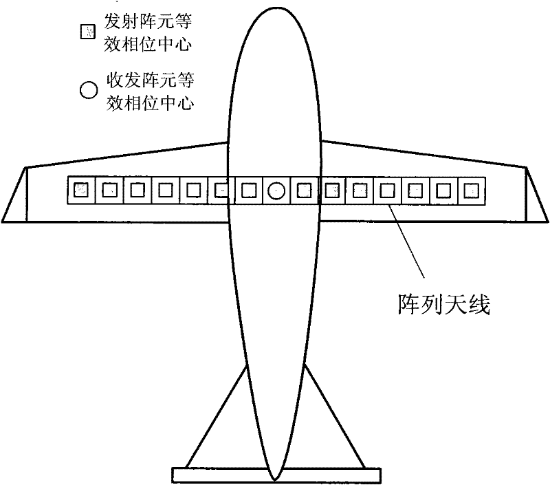
[0063] System constitution of the present invention is with embodiment 1. Refer to image 3 , the phased array antenna of the present invention is placed on the wing of the aircraft, and the placement direction is perpendicular to the flight direction of the aircraft. The phased array antenna can be uniformly densely distributed or sparsely distributed to reduce system hardware costs. For the convenience of analysis, the phased array antenna in this example adopts a uniform and dense array, and the single receiving element in the phased array antenna array is a receiving and transmitting element, which can be selected as any element in the phased array antenna One array element, but due to geometric symmetry, its best position is in the center of the phased array antenna array. The vertical heading dimension D of the array element a It should be satisfied that its vertical heading beam width is slightly larger than the vertical heading mapping bandwidth W y , which satisfies...

Embodiment 3

[0068] The present invention is also an airborne down-looking three-dimensional synthetic aperture radar imaging method based on transmitting beam scanning, the method is implemented on an airborne down-looking three-dimensional synthetic aperture radar imaging system, see image 3 , the present invention is a multi-transmission and single-reception system. When transmitting, all array elements of the phased array antenna work simultaneously; when receiving, only a single array element works. The specific steps include:

[0069] Step 1. The radar transmitter uses the transmit beamforming technology to weight the signals of different transmit channels through preset weighting factors to form narrow beams with different preset directions in the vertical direction. See figure 2 ;

[0070] Step 2. The phased array antenna transmits the narrow beams generated by the radar transmitter one by one, scans the vertical direction with narrow beams at each azimuth time, and finally reali...


PUM


Abstract

The invention discloses an airborne three-dimensional synthetic aperture radar imaging system based on transmitted beam scanning. In the current three-dimensional synthetic aperture radar imaging system, echo data volume is large, imaging processing is complex and timeliness is low. Using the airborne three-dimensional synthetic aperture radar imaging system of the invention can solve the above problems. In the invention, a radar transmitter generates narrow wave beams possessing different preset orientations in a vertical heading by using a transmitted beam forming technology. A phased-arrayantenna, which is arranged vertically to the heading in a flight plane, successively transmits the narrow wave beams generated by the radar transmitter one by one. Narrow wave beam scanning to the vertical heading can be performed in every direction at any time. The echo is received by a single array element of the phased-array antenna and is sent to a radar receiver so as to complete acquisitionof single channel echo data. An imaging processor can be used to three-dimensionally image the collected echo data. By using the invention, echo data volume is small, imaging processing is not complex and timeliness is strong. And the system has the ability of rapid three dimensional imaging an object scene, especially the complex object scene.

Description

technical field [0001] The invention belongs to the technical field of radar, and mainly relates to an airborne radar imaging system, in particular to an airborne down-looking three-dimensional synthetic aperture radar imaging system, which can be used for three-dimensional high-resolution imaging of a target scene by an airborne three-dimensional synthetic aperture radar. Background technique [0002] Downward-looking three-dimensional synthetic aperture radar (Three-dimensional Synthetic Aperture Radar, 3D-SAR) is a new system radar, which is based on the traditional two-dimensional SAR imaging principle (using pulse compression technology to obtain high Aperture principle obtains high resolution in azimuth), and introduces linear array antennas in the vertical direction (referred to as vertical direction) in the flight plane to form a real aperture, thus having the third dimension beyond the two-dimensional resolution capabilities of traditional two-dimensional SAR in the ...

Claims


Application Information

Patent Timeline
IPC IPC(8): G01S13/90G01S7/03
Inventor 李真芳徐有栓索志勇郭交刘艳阳杨桃丽
Owner XIDIAN UNIV
Why Eureka
Try Eureka