Realization method of business process and workflow engine
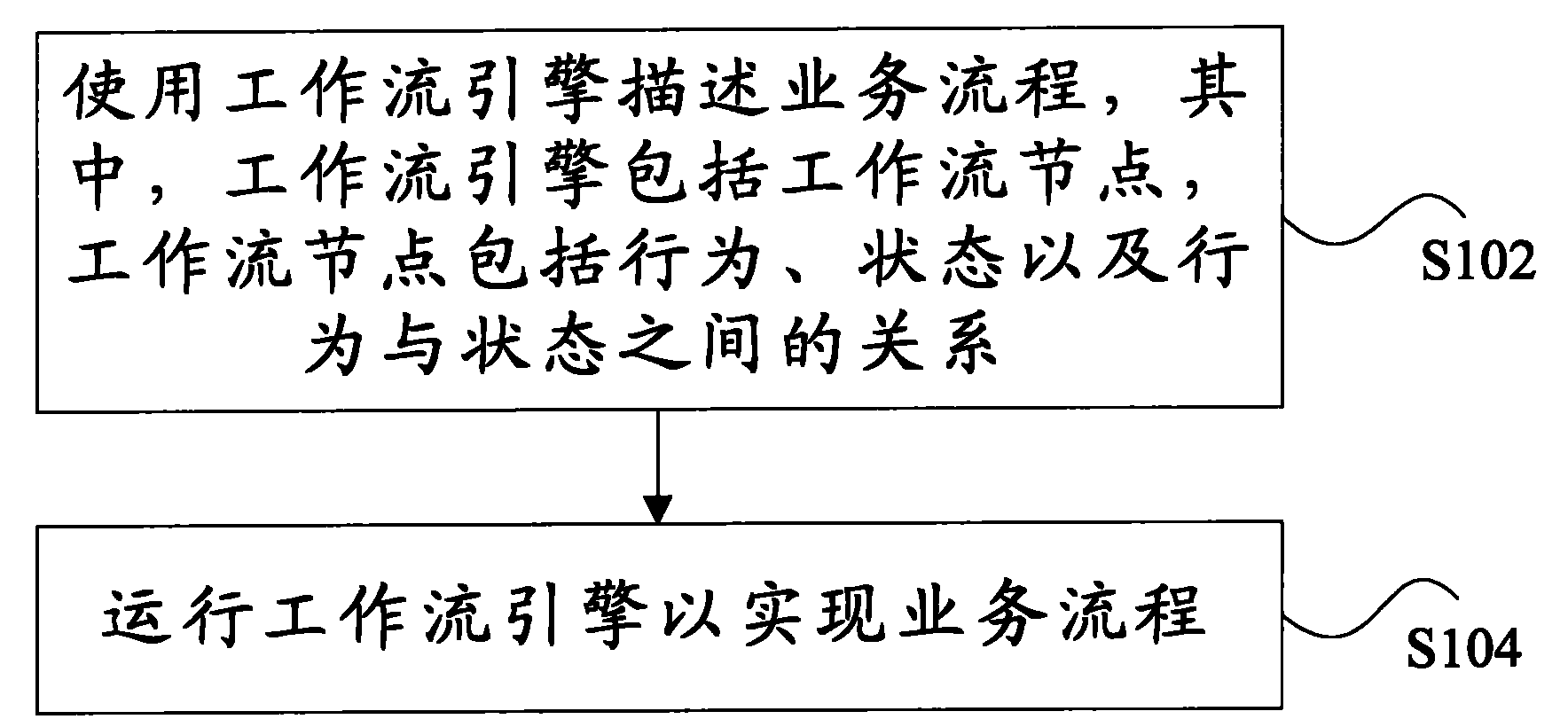
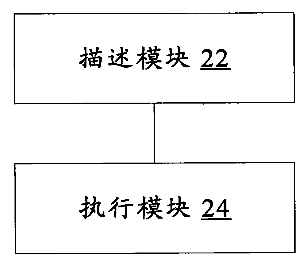
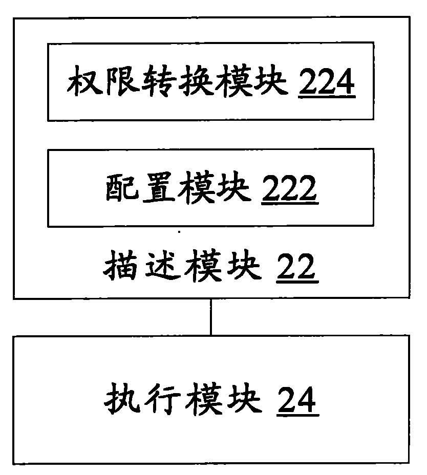
A workflow engine and business process technology, applied in the direction of instruments, data processing applications, resources, etc., can solve the problems of increasing system development and maintenance costs, abstraction, and difficulty in maintenance, so as to reduce the development cycle and maintenance costs, Expand the application field and improve the effect of user experience
- Summary
- Abstract
- Description
- Claims
- Application Information
AI Technical Summary
Problems solved by technology
Method used
Image
Examples
example 1
[0051] Figure 4 is a structural block diagram of the workflow engine system according to Example 1 of the present invention, such as Figure 4 As shown, the workflow engine system 40 includes: a workflow engine and business process definition subsystem 42 and a workflow engine background processing subsystem 44 . The structure will be described in detail below.
[0052] The workflow engine and business process definition subsystem 42 provides visual definition and configuration tools to complete the processing mechanism of the workflow engine and the flow chart of specific business processes. That is, the definition and configuration data related to workflow engine, business process, etc. are finally output.
[0053] In the specific implementation process, the definition of the processing mechanism of the workflow engine can include the definition of how many behaviors and states exist in the workflow nodes, and the relationship between behaviors and states, and is also res...
example 2
[0058] Figure 5 is a structural block diagram of the workflow engine system according to Example 2 of the present invention, such as figure 2 As shown, the workflow engine background processing subsystem 44 includes: an interface module 442 , an execution engine module 444 , and a data persistence module 446 . The structure will be described in detail below.
[0059] The interface module 442 is used to provide rich interactive interfaces (for example, API interface, WebService interface and database interface, etc.) to the application system that needs to integrate the workflow engine, and to receive messages from the application system. After the interface module 442 receives the request message from the application system, it is processed by the execution engine module 444 and returns the processing result message to the application system. This ensures that the workflow engine can be applied to various application systems.
[0060] The execution engine module 444 is us...
example 3
[0068] Figure 6 is a schematic structural diagram of a workflow engine system according to Example 3 of the present invention, such as Figure 6 As shown, the implementation method of the workflow engine system may include the following steps:
[0069] Step S602 , defining workflow engine and business process in workflow engine and business process definition environment 62 . Among them, the workflow engine and business process definition environment 62 is a visual definition tool, which can define the processing mechanism of the workflow engine (including the behavior, status and relationship between business processes), and can A variety of business flow charts can be defined, and their interaction methods can be configured between the workflow engine and the application system. The relevant data defined by this tool will be used as the basic data for the workflow engine to support the operation of business processes, and these data will be applied in many subsequent step...
PUM
 Abstract
Description
Claims
Application Information
 - R&D
- Intellectual Property
- Life Sciences
- Materials
- Tech Scout
- Unparalleled Data Quality
- Higher Quality Content
- 60% Fewer Hallucinations
Browse by: Latest US Patents, China's latest patents, Technical Efficacy Thesaurus, Application Domain, Technology Topic, Popular Technical Reports.
© 2025 PatSnap. All rights reserved.Legal|Privacy policy|Modern Slavery Act Transparency Statement|Sitemap|About US| Contact US: help@patsnap.com


