Back electrode design method for reducing unit consumption

A backside electrode and design method technology, applied in the direction of circuits, electrical components, sustainable manufacturing/processing, etc., can solve the problems of high production costs, achieve the effects of reducing welding difficulty, saving paste, and reducing expansion coefficient

Inactive Publication Date: 2011-11-23
ZHEJIANG FORTUNE ENERGY
View PDF4 Cites 3 Cited by
  • Summary
  • Abstract
  • Description
  • Claims
  • Application Information

AI Technical Summary

Problems solved by technology

[0003] The purpose of the present invention is to provide a method for designing the back electrode with reduced unit consumption, and to solve the problem of high production cost in the prior art

Method used


Image

  • Back electrode design method for reducing unit consumption
  • Back electrode design method for reducing unit consumption
  • Back electrode design method for reducing unit consumption

Examples


Embodiment 1

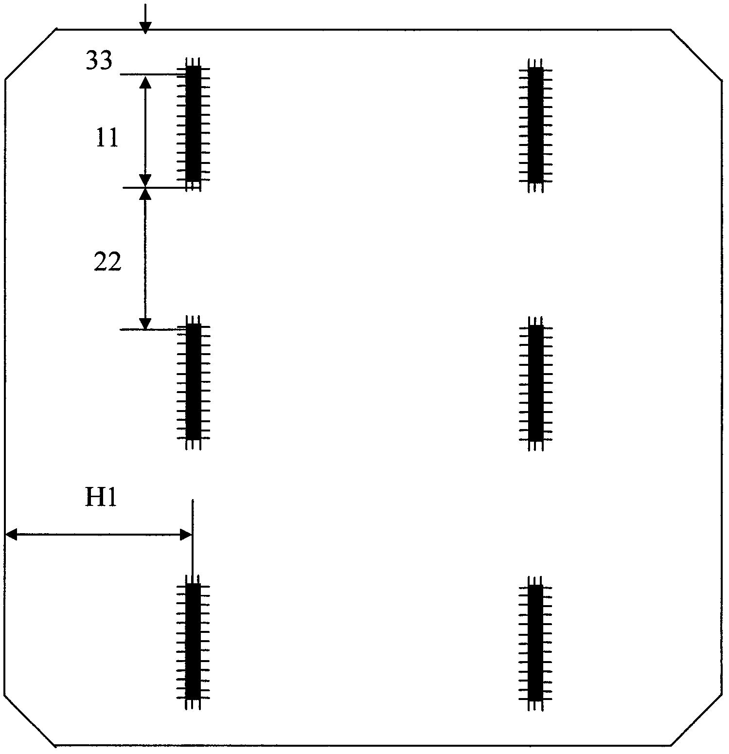
[0021] The design size of the back electrode obtained by the method of the present invention is that the size 11 of each segment electrode is 10mm, the distance 22 between the electrodes at adjacent two ends is 20mm, and the size of the distance 33 between each electrode end and the edge of the silicon chip is 5mm, the size of the horizontal distance H1 between each electrode and the edge of the silicon wafer is 31.25mm, the width of each electrode is 3mm and is not hollowed out, the length of the sawtooth is 1.2mm, and the width is 0.4mm. Root sawtooth, the distance between adjacent sawtooth is 0.5mm.

[0022] Using the same parameter screen provided by the same manufacturer and under the same experimental conditions, the comparison of the experimental data between the scheme of two complete non-segmented electrodes in the prior art and the design scheme of the present invention is shown in Table 1 and Table 2.

[0023] Table 1 is the printed wet weight of two schemes, the pr...

Embodiment 2

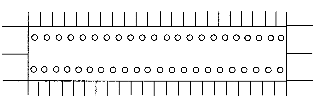
[0030] The design method of the back electrode used in this embodiment is the same as that in Embodiment 1, the manufacturers providing the corresponding screen plates for the back electrode are different, and the parameters are slightly changed. The size 11 of each segment electrode is 25mm, the distance 22 between the electrodes at adjacent two ends is 30mm, the size of the distance 33 between the end of each electrode and the edge of the silicon wafer is 10mm, and the horizontal distance H1 between each electrode and the edge of the silicon wafer The size of the electrode is 31.25mm, the width of each electrode is 3mm and it is not hollowed out, the length of the sawtooth is 0.8mm, the width is 0.8mm, 15 sawtooths are evenly distributed on each section, and the distance between adjacent sawtooth is 0.7mm.


PUM


Abstract

The invention discloses a back electrode design method for reducing unit consumption. The back electrode design method for reducing unit consumption comprises the following steps of: A, designing back electrodes into two parallel electrodes having the same structure, wherein the distance between an end part of each electrode and an edge of a silicon chip is 5 to 10mm; B, forming sawteeth at the periphery of each electrode, wherein the sawteeth have the width of 0.4 to 0.8mm, and a space between two adjacent sawteeth is 0.5 to 0.7mm; C, forming two columns of holes on each electrode, wherein the holes are formed at the same interval corresponding to hollow parts of the sawteeth; and D, equally segmenting each electrode into three sections, wherein each section has the length of 10 to 25mm, a space between two adjacent sections of the electrode is 20 to 30mm, and the dimension of each section of the electrode is different from the space between the two adjacent sections of the electrode. The invention has the advantages that: each electrode is segmented into three sections, an expansion coefficient can be reduced, the component welding difficulty is reduced, paste is saved, and the production cost is reduced.

Description

technical field [0001] The invention relates to a back electrode of a solar cell, in particular to a design method for the back electrode which reduces unit consumption. Background technique [0002] As the world's demand for new energy increases, the sales of solar cells are getting better and better, and the back electrode is an important part of solar cells. A back electrode in the prior art such as figure 1 As shown, it consists of two electrodes with the same structure. However, when the back electrode is screen-printed, more paste is used, the cost is higher, and the coefficient of expansion is also higher. Contents of the invention [0003] The purpose of the present invention is to provide a method for designing the rear electrode with reduced unit consumption, so as to solve the problem of high production cost in the prior art. [0004] The technical solution adopted in the present invention is to provide a method for designing the back electrode that reduces u...

Claims


Application Information

Patent Timeline
Patent Type & Authority Applications(China)
IPC IPC(8): H01L31/18
CPCY02P70/50
Inventor 张健俞超
Owner ZHEJIANG FORTUNE ENERGY
Why Eureka
Try Eureka