Single-phase inverter for eliminating ripples wave at direct current input end and solar photovoltaic generating system

A single-phase inverter, DC input technology, used in photovoltaic power generation, optical radiation generators, energy storage systems, etc., can solve the problems of reduced life, complex circuits and control methods, capacitor self-heating, etc. The effect of frequency ripple

Active Publication Date: 2011-11-23
ALTENERGY POWER SYST
View PDF2 Cites 7 Cited by
  • Summary
  • Abstract
  • Description
  • Claims
  • Application Information

AI Technical Summary

Problems solved by technology

[0007] Generally, inverters use large-capacity electrolytic capacitors on the DC main line as passive filters, but electrolytic capacitors have multiple failure modes, especially ripple currents that cause internal self-heating of capacitors and shorten life spans
Active filter circuits have been widely studied to replace passive methods by providing another ripple that cancels out the dual-frequency ripple power through a separate energy conversion circuit, but this method requires complex circuits and control methods

Method used


Image

  • Single-phase inverter for eliminating ripples wave at direct current input end and solar photovoltaic generating system
  • Single-phase inverter for eliminating ripples wave at direct current input end and solar photovoltaic generating system
  • Single-phase inverter for eliminating ripples wave at direct current input end and solar photovoltaic generating system

Examples


Embodiment Construction

[0064] The present invention will be further described below in conjunction with specific embodiment and accompanying drawing, set forth more details in the following description so as to fully understand the present invention, but the present invention can obviously be implemented in a variety of other ways different from this description, Those skilled in the art can make similar promotions and deductions based on actual application situations without violating the connotation of the present invention, so the content of this specific embodiment should not limit the protection scope of the present invention.

[0065] An embodiment of a single-phase inverter that eliminates ripple at the DC input

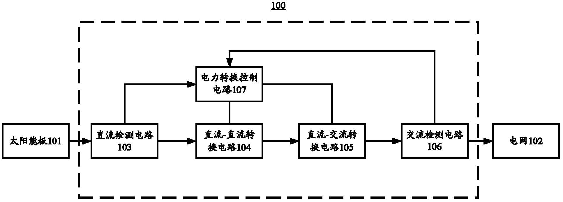
[0066] image 3 It is a schematic diagram of a module structure of a single-phase inverter for eliminating ripple at a DC input terminal according to an embodiment of the present invention. As shown in the figure, the single-phase inverter 300 is connected between a solar panel 301...


PUM


Abstract

The invention provides a single-phase inverter for eliminating ripple waves at a direct current input end. The single-phase inverter is connected between a direct current input end and an alternated current output end and comprises a direct current detection circuit, an alternated current detection circuit, a direct current-direct current conversion circuit, a direct current-alternated current conversion circuit, an electric conversion control circuit and a ripple wave eliminating unit, wherein the ripple wave eliminating unit is used for eliminating the ripple waves at the direct current input end according to an input direct current electric signal and an output alternated current electric signal; the ripple wave eliminating unit comprises a ripple wave controller, an energy storage unit and an energy storage controller; the ripple wave controller is used for controlling a working mode of the ripple wave eliminating unit according to the input direct current electric signal and the output alternated current electric signal; the energy storage unit is used for storing or releasing the energy at the direct current input end; and the energy storage controller is used for controlling the switching on and off of the energy storage unit. The invention also provides a solar photovoltaic generating system. In the single-phase inverter provided by the invention, under the condition of utilizing the ripple wave eliminating unit to detect a ripple wave power and control the working mode of a conversion circuit, a voltage on a capacitor changes following an energy waveform and can be controlled to be equal to the ripple wave power, thereby realizing charging and discharging and eliminating the ripple waves at the direct current input end.

Description

technical field [0001] The invention relates to the technical field of power conversion, in particular, the invention relates to a single-phase inverter and a solar photovoltaic power generation system for eliminating ripples at a DC input terminal. Background technique [0002] Many renewable energy sources generate DC electricity, such as solar photovoltaics and chemical batteries. The direct current is converted into a fixed-frequency sinusoidal alternating current through an inverter, and then transmitted to the grid or used off-grid. [0003] Inverters for solar photovoltaic power generation systems have recently tended to adopt distributed micro-inverters (micro-inverters). The micro-inverter provides maximum power point control for each DC photovoltaic module, so that each DC photovoltaic module can generate the maximum energy and improve the performance of the entire solar photovoltaic power generation system. In addition, the micro-inverter can also generate AC lo...

Claims


Application Information

Patent Timeline
Patent Type & Authority Applications(China)
IPC IPC(8): H02M1/14H02J15/00H02N6/00H02J3/38
CPCY02E70/30Y02E10/563Y02E10/56
Inventor 罗宇浩
Owner ALTENERGY POWER SYST
Why Eureka
Try Eureka