Charging and discharging control system and control method thereof

A charge and discharge control and control method technology, applied in battery/fuel cell control devices, charging stations, battery circuit devices, etc., can solve the problems of increasing failure points, increasing costs, and the number of multiple components, and reducing the number of components. Quantity, the effect of reducing control costs

Pending Publication Date: 2020-03-06
HUBEI JINQUAN NEW MATERIALS CO LTD
View PDF4 Cites 2 Cited by
  • Summary
  • Abstract
  • Description
  • Claims
  • Application Information

AI Technical Summary

Problems solved by technology

The above two methods of controlling the charging and discharging of electric vehicles require a large number of components, increase the cost, and increase the failure point in the program control

Method used


Image

  • Charging and discharging control system and control method thereof
  • Charging and discharging control system and control method thereof
  • Charging and discharging control system and control method thereof

Examples


Embodiment 1

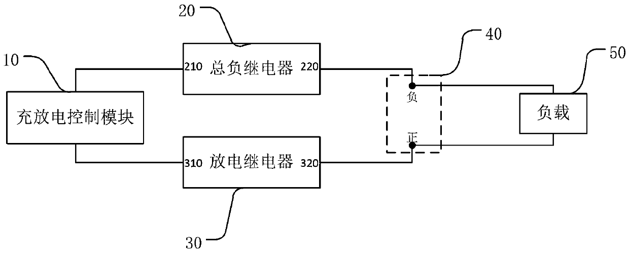
[0032] figure 2 A schematic structural diagram of the charging and discharging control system provided in Embodiment 1 of the present invention, as shown in figure 2 As shown, the charge and discharge control system includes: a charge and discharge control module 10, a total negative relay 20, a discharge relay 30 and a charge and discharge port 40, one end of the charge and discharge control module 10 is connected to the first end 210 of the total negative relay 20, and the charge and discharge control The other end of the module 20 is connected to the first end 310 of the discharge relay 30, the second end 220 of the total negative relay 20 is connected to the negative pole of the charge and discharge port 40, the second end 320 of the discharge relay 30 is connected to the positive pole of the charge and discharge port 40, and the charge and discharge The control module 10 is used to control the on-off state of the total negative relay 20 and the discharge relay 30 accord...

Embodiment 2

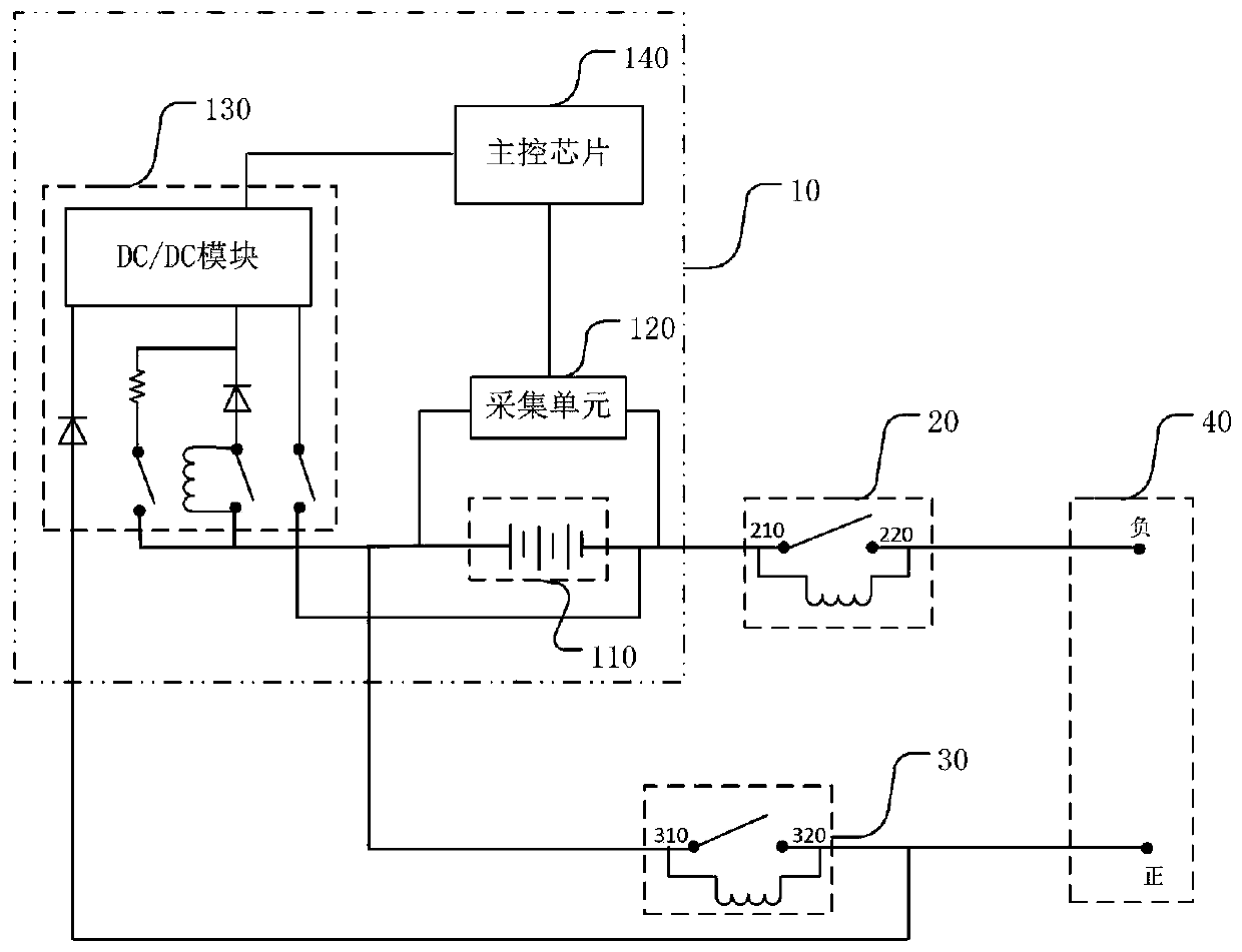
[0044] image 3 A schematic structural diagram of the charging and discharging control system provided in Embodiment 2 of the present invention, as shown in image 3 As shown, the charge and discharge control module 10 includes a battery assembly 110, an acquisition unit 120, a voltage conversion unit 130, and a main control chip 140. The positive pole 111 of the battery assembly 110 is electrically connected to the first end 310 of the discharge relay 30, and the negative pole of the battery pack 110 112 is electrically connected to the first end 210 of the main negative relay 20, and is used for charging and discharging according to the charging rule and the discharging rule.

[0045] Wherein, the positive pole 111 of the battery assembly 110 is electrically connected to the first end 310 of the discharge relay 30, and the negative pole 112 of the battery pack 110 is electrically connected to the first end 210 of the total negative relay 20, and the charge and discharge rela...

Embodiment 3

[0063] Figure 5 The flow chart of the control method of the charging and discharging control system provided by Embodiment 3 of the present invention, as shown in Figure 5 As shown, the control method of the charging and discharging control system includes:

[0064] S100 , in the charging stage, the charging and discharging control module controls the on-off states of the total negative relay and the discharging relay according to the charging rules to perform charging control.

[0065] Optionally, the charging rule includes controlling the discharge relay and the total negative relay to be sequentially closed to turn on the charging path, and then controlling the total negative relay and the discharge relay to be sequentially opened to disconnect the charging path.

[0066] S200 , in the discharge stage, the charge and discharge control module controls the on-off state of the total negative relay and the discharge relay according to the discharge rule to perform discharge ...


PUM


Abstract

The invention discloses a charging and discharging control system and a control method thereof. The charging and discharging control system comprises a charging and discharging control module, a mainnegative relay, a discharging relay and a charging and discharging port. One end of the charging and discharging control module is connected with the first end of the main negative relay, the other end of the charging and discharging control module is connected with the first end of the discharging relay, the second end of the main negative relay is connected with a negative electrode of the charging and discharging port, and the second end of the discharging relay is connected with a positive electrode of the charging and discharging port. The charging and discharging control module is used for controlling the on-off states of the main negative relay and the discharging relay according to a charging rule so as to perform charging control, and controlling the on-off states of the main negative relay and the discharging relay according to a discharging rule so as to perform discharging control. According to the embodiment of the invention, the charging and discharging of the charging and discharging control system are realized through one main negative relay and one discharging relay, the number of components in the charging and discharging control system is reduced, and the controlcost is reduced.

Description

technical field [0001] The invention relates to the field of power battery control, in particular to a charge and discharge control system and a control method for the charge and discharge control system. Background technique [0002] In the field of in-vehicle electronic equipment and the like, relays are used to switch the state of power supply. [0003] In the existing way of controlling the charging and discharging of electric vehicles, if the charging interface and the discharging interface are separated, two high-voltage circuits are required to control the charging and discharging separately, and the circuit is complicated. If the charging interface and the discharging interface are one interface, it is necessary to set a charging relay, a discharging relay and two diodes in the same high-voltage circuit to control the switching of charging and discharging modes. Both of the above two methods of controlling the charging and discharging of electric vehicles require a ...

Claims


Application Information

Patent Timeline
Patent Type & Authority Applications(China)
IPC IPC(8): H02J7/00B60L53/00B60L58/10B60L58/18
CPCH02J7/0068H02J7/0013B60L53/00B60L58/10B60L58/18Y02T10/70Y02T10/7072Y02T90/14
Inventor 丁春貌刘士玉陈文涛江吉兵刘金成
Owner HUBEI JINQUAN NEW MATERIALS CO LTD
Why Eureka
Try Eureka