Switched capacitor type DC/DC converter, switching power supply and control method

A DC converter, switched capacitor technology, applied in the direction of converting DC power input to DC power output, adjusting electrical variables, control/regulating systems, etc., can solve the problems of large power supply, large PCB area, and difficulty in thinning the thickness.

Active Publication Date: 2021-02-02
HUAWEI DIGITAL POWER TECH CO LTD
View PDF1 Cites 2 Cited by
  • Summary
  • Abstract
  • Description
  • Claims
  • Application Information

AI Technical Summary

Problems solved by technology

[0006] figure 1 The main disadvantage of the DC / DC converter shown is that it includes the transformer T. Since the transformer T needs to include primary windings, secondary windings and magnetic cores, the volume is small, so the volume of the power supply is large, and the thickness is difficult to be thinned. In order to reduce the volume , can only be achieved by increasing the switching frequency, but increasing the switching frequency will increase the function, resulting in a decrease in power supply efficiency
Generally, during implementation, the primary winding and secondary winding of the transformer need to be coupled, and there is repeated coupling current, which requires more PCB area to flow through, limiting the reduction of power supply area

Method used


Image

  • Switched capacitor type DC/DC converter, switching power supply and control method
  • Switched capacitor type DC/DC converter, switching power supply and control method
  • Switched capacitor type DC/DC converter, switching power supply and control method

Examples


Embodiment 1

[0060] The switched capacitor DC / DC converter provided in this embodiment includes: a controllable switch and n switched capacitor modules; n is an integer greater than or equal to 1; when the DC / DC converter implements different voltage ratios, n can be Take different values, for example, when n=1, the voltage transformation ratio realized by the DC / DC converter is 2:1; when n=2, the voltage transformation ratio realized by the DC / DC converter is 2:1 ; When n=3, the voltage transformation ratio realized by the DC / DC converter is 5:1; when n=4, the voltage transformation ratio realized by the DC / DC converter is 8:1; when n=5 , the DC / DC converter achieves a voltage transformation ratio of 13:1, and so on.

[0061] The n switched capacitor modules are connected in series to form a voltage transformation branch, and the voltage transformation branch is connected in series with the controllable switch. Each switched capacitor module has the same structure as Figure 3A As shown...

Embodiment 2

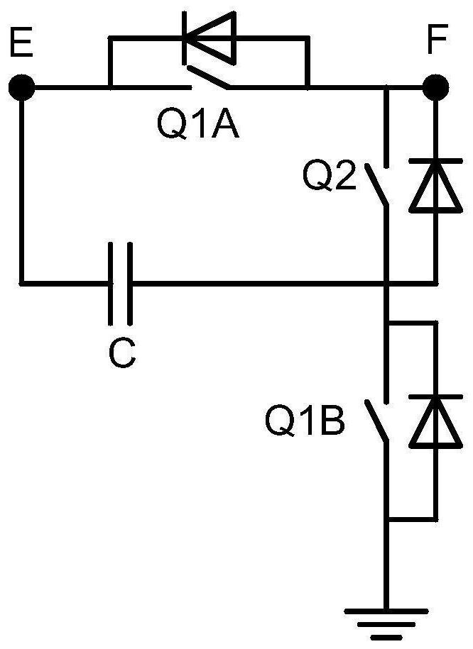
[0130] In order to suppress or reduce the inrush current that the capacitor in each switched capacitor module bears during charging, an inductor can be added to each switched capacitor module, specifically, it can be added at a position connected in series with the capacitor.

[0131] see Figure 14 , which is a schematic diagram of another switched capacitor DC / DC converter provided in the embodiment of the present application.

[0132] This embodiment provides another switched capacitor DC / DC converter. Figure 14 Taking n=4 as an example for introduction, this scheme is applicable to n being any integer.

[0133] In the switched capacitor DC / DC converter provided in this embodiment, each switched capacitor module further includes an inductor;

[0134] The inductor and the capacitor are connected in series to the first node and the second end of the second switch tube. Since the inductor has the ability to suppress sudden changes in current, such as Figure 14 As shown, ...

Embodiment 3

[0138] Figure 14 In the introduction, each switched capacitor module includes an inductor as an example. In order to reduce the overall volume of the converter and reduce costs, inductors can also be installed in some switched capacitor modules instead of each switched capacitor module. inductance.

[0139] see Figure 15 , which is a schematic diagram of another switched capacitor DC / DC converter provided in the embodiment of the present application.

[0140] In the converter provided in this embodiment, the way of setting the inductance is only applicable when n is an odd number. The inductor and the capacitor are connected in series to the first node and the second end of the second switch tube;

[0141] When the n is an odd number, start from the first end connected to the controllable switch, that is, sequentially number the switched capacitor modules from the high voltage side to the low voltage side, and number the switched capacitor modules with odd numbers in the ...


PUM


Abstract

The invention discloses a switched capacitor type DC / DC converter, a switching power supply and a control method. The switched capacitor type DC / DC converter comprises a controllable switch and n switched capacitor modules, the n switched capacitor modules are connected in series to form a voltage transformation branch, and the voltage transformation branch is connected with the controllable switch in series, and n is an integer greater than or equal to 1. When the DC / DC converter realizes different voltage transformation ratios, n can take different values, for example, when n is equal to 1,the voltage transformation ratio realized by the DC / DC converter is 2: 1; when n is equal to 2, the voltage transformation ratio realized by the DC / DC converter is 2: 1; when n is equal to 3, the voltage transformation ratio realized by the DC / DC converter is 5: 1; when n is equal to 4, the voltage transformation ratio realized by the DC / DC converter is 8: 1; and when n is equal to 5, the voltagetransformation ratio realized by the DC / DC converter is 13: 1, and so on. The converter can realize buck or boost, and does not internally comprise a transformer, so that the volume of the whole converter is reduced.

Description

technical field [0001] The present application relates to the technical field, and in particular to a switched capacitor type DC / DC DC / DC converter, a switching power supply and a control method. Background technique [0002] At present, switching power supplies are widely used in various electrical equipment to provide electrical equipment that meets the requirements. [0003] For example, when the application scenarios are AI and data centers, the power supply voltage of service boards is generally 48V. The power supply voltage of the chip and various loads inside the business board needs to be lower than 48V, that is, the power supply voltage of the business board cannot directly supply power to the chip and various loads, and generally requires at least two stages of step-down processing. Usually the first stage of step-down is to step down 48V to 12V, and the second stage of step-down is to step down 12V to 5V, 3.3V and 1.8V to supply power for chips and various loads....

Claims


Application Information

Patent Timeline
Patent Type & Authority Applications(China)
IPC IPC(8): H02M3/156H02M1/088H02M1/32
CPCH02M3/156H02M1/088H02M1/32H02M1/322H02M1/0058Y02B70/10H02M3/07H02M3/072H02M1/0077H02M3/1582
Inventor 何正言程杰斌谌海涛
Owner HUAWEI DIGITAL POWER TECH CO LTD
Why Eureka
Try Eureka