
Lifting device for transfer plate at the end of printing machine

A lifting device and printing machine technology, which is applied to printing machines, rotary printing machines, screen printing machines, etc., can solve the problems of large investment in factories, difficult acceptance by enterprises, prolonging the flash drying time of flash ovens, and ink drying speed, etc. Achieve the effect of reducing the occupied area

Inactive Publication Date: 2011-11-30
常州市奥伦自动化设备有限公司
View PDF0 Cites 3 Cited by
  • Summary
  • Abstract
  • Description
  • Claims
  • Application Information

AI Technical Summary

Problems solved by technology

Although the first two solutions have certain effects, adding cooling and drying stations will not only increase the cost of the printing machine, but more importantly, increase the floor space and space of the equipment, and require a large investment in factory buildings, which is difficult for enterprises to accept.
The method of reducing the transmission speed of the entire printing production line will directly affect the production efficiency of the entire printing production line, and the production enterprises are not willing to accept it.
Prolong the flash drying time of the flash oven. The ink drying speed is too fast, and the pattern is easy to warp, which also affects the quality of fabric printing, and the qualified rate of the product cannot be guaranteed.

Method used


Image

  • Lifting device for transfer plate at the end of printing machine
  • Lifting device for transfer plate at the end of printing machine
  • Lifting device for transfer plate at the end of printing machine

Examples


Embodiment 1

[0018] Embodiment 1: The transfer plate lifting device at the end of the printing machine, such as Figure 8 , Figure 9 , Figure 10 As shown, it includes a lifting tray 1, two cylinder units 2, a fixed support frame 3 and a frame 4, and the cylinder unit 2 includes a cylinder block 21 of the first cylinder, a piston rod 22 of the first cylinder, and a connecting plate 23 1. The cylinder body 24 of the second cylinder and the piston rod 25 of the second cylinder, one end of the fixed support frame 3 is fixedly connected with the cylinder body 21 of the first cylinder, and the other end is fixedly connected with the frame 4; one end of the connecting plate 23 is connected with the first cylinder The upper end surface of the piston rod 22 is fixedly connected, and the other end is fixedly connected with the cylinder body 24 of the second cylinder, and the lifting disc 1 is fixed on the piston rod 25 of the second cylinder, after the two cylinder units 2 are connected with the ...

Embodiment 2

[0019] Embodiment 2: Change the cylinder unit 2 in Embodiment 1 into a large-stroke cylinder, and the cylinder body is fixedly connected with the frame 4 through the fixed support frame 3; the lifting disc 1 is fixed on the piston rod of the cylinder.

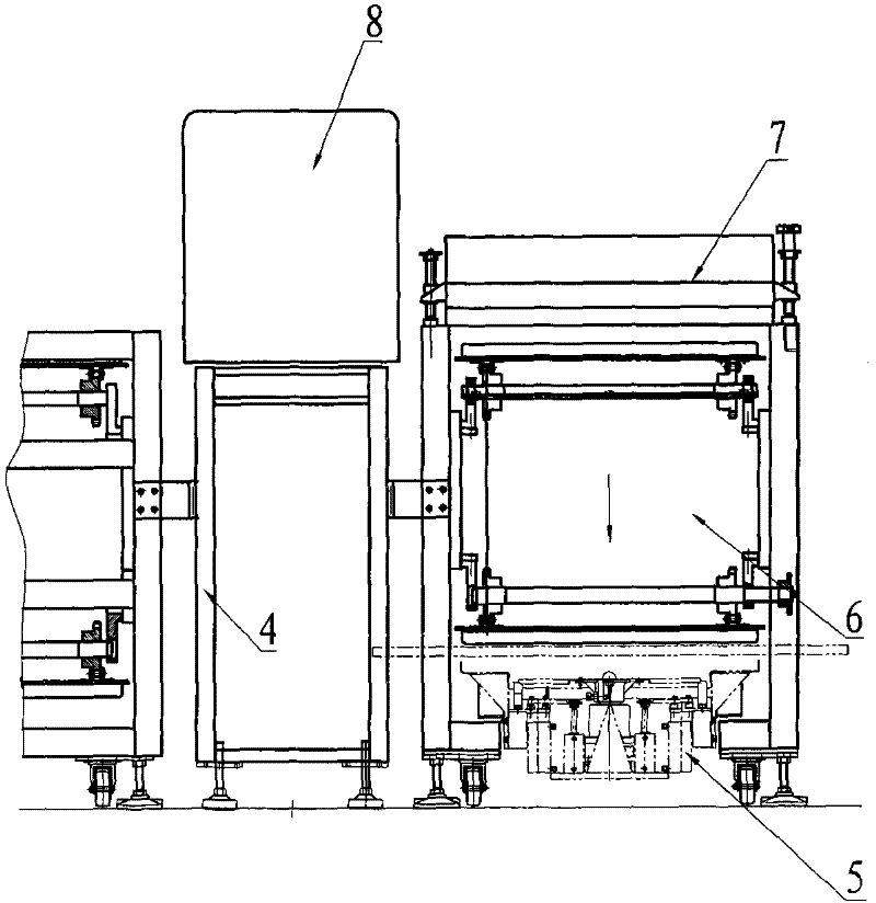
[0020] The working process of the present invention is as follows: when the transfer plate 10 is sent from the outer conveying mechanism of the printing line to the print head 8 station at the end, after printing, it enters the flash oven 7 station for flash drying, and then enters the synchronous descending sequence after flash drying. Mechanism 6, when the transfer plate 10 is transported to the lowest position, the transfer plate lifting and steering device 5 will carry out the actions of receiving, descending, rotating 180°, and descending in sequence, so that the transfer plate 10 will be placed horizontally on the horizontal conveyor belt 11 to carry out translation, enter the below of the synchronous lifting mechanism 9, ...


PUM


Abstract

A lifting device for a transfer plate at the end of a printing machine, which includes a lifting plate, two cylinder units, a fixed support frame and a frame, the cylinder unit includes a fixed cylinder body and a moving piston rod, and one end of the fixed support frame It is fixedly connected with the fixed cylinder body, and the other end is fixedly connected with the frame; the lifting plate is fixed on the upper end surface of the piston rod. It cooperates with the lifting and steering device of the transfer board and the horizontal conveyor belt below the synchronous lowering station to complete the receiving, lowering, rotating 180° of the transfer board in sequence, then lowering and lowering, translation and lifting, and finally feeding In the synchronous lifting mechanism, the linear transition between the two ends of the printing machine is realized, and the entire line realizes continuous printing without intervals, which can reduce the footprint of the printing machine and improve the printing efficiency of the entire printing machine.

Description

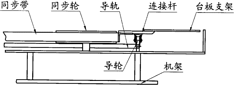
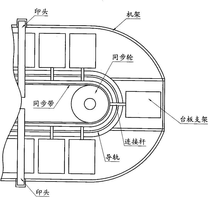
Technical field: [0001] The invention relates to a printing machine with a vertical process delay curing function, in particular to a linear transition device at both ends. Background technique: [0002] In the traditional circular printing machine, the two ends are semicircular transition sections, such as figure 1 , figure 2 As shown, the transfer table is a flat plate of 600×800mm. The transfer board is placed on the table support. The table support cooperates with the guide rail through the connecting rod. Drive the synchronous belt, and the platen bracket moves along the guide rail with the connecting rod. The transmission mode is directional and horizontal interval movement. After the printing and flash drying process is completed, it usually passes through three ink curing stations. During flash drying, only the printing ink can be used The surface layer dries quickly, and the deep layer of the printing ink is still in a creeping state. Due to the short path from t...

Claims


Application Information

Patent Timeline
Patent Type & Authority Applications(China)
IPC IPC(8): B41F15/16
Inventor 王永鑫
Owner 常州市奥伦自动化设备有限公司
Learn More