
Separate two-phase anaerobic fermentation fermentation device

An anaerobic fermentation and fermentation device technology, which is applied in the field of separate two-phase anaerobic fermentation and fermentation devices, can solve the problems of difficulty in feeding and discharging materials, high labor costs, secondary pollution, etc., so as to reduce the risk of methane leakage, maintain and manage The effect of convenience and reduction of project cost

Inactive Publication Date: 2011-11-30
衢州市土肥与农村能源技术推广站 +1
View PDF7 Cites 18 Cited by
  • Summary
  • Abstract
  • Description
  • Claims
  • Application Information

AI Technical Summary

Problems solved by technology

[0008] However, when the above-mentioned research results and patented technologies involve straw as a raw material, it is proposed that pretreatment such as composting or crushing is required, and it is difficult to feed and discharge materials, and the operation requirements are high, and the cost of straw crushing is high, and the working conditions and environment In addition, Zhu Jin et al. (2011) compared two-phase and single-phase fermentation of straw and found that if the phase separation in the two-phase process is not good , because the methanogenic bacteria in the methanogenic phase continuously enter the hydrolysis and acidification tank, the proportion of biogas produced in the final hydrolysis and acidification phase accounts for 79.52% of the total biogas production, and the hydrolysis and acidification phase is often open, which will inevitably lead to a large amount of methane , carbon dioxide and other greenhouse gases, which runs counter to the concept of low-carbon and recycling technology of biogas projects; thirdly, existing biogas projects will produce a large amount of biogas slurry, if it is not properly used and discharged randomly, it will inevitably cause secondary pollution. secondary pollution or increase the burden of subsequent purification treatment, and the current technologies and patents have not effectively solved these practical problems

Method used


Image

  • Separate two-phase anaerobic fermentation fermentation device
  • Separate two-phase anaerobic fermentation fermentation device
  • Separate two-phase anaerobic fermentation fermentation device

Examples


Embodiment Construction

[0028] The accompanying drawings disclose the specific structure of the embodiment of the present invention without limitation, and this embodiment will be further described below in conjunction with the accompanying drawings.

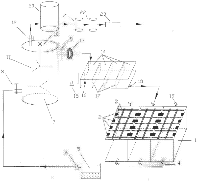
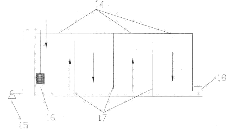
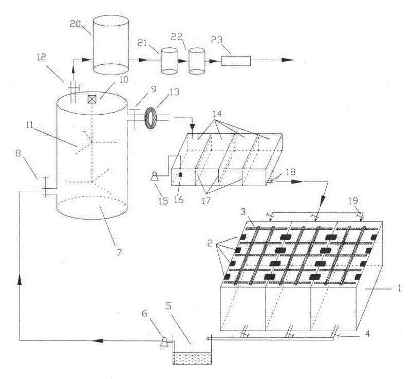
[0029] Depend on figure 1 and figure 2 It can be seen that the separated two-phase anaerobic fermentation fermentation device includes a hydrolysis acidification reaction device, anaerobic fermentation device and biogas slurry oxidation device, of which:

[0030] The hydrolysis acidification reaction device includes 2 to 6 parallel hydrolysis acidification basic units of hydrolysis acidification reaction tank 1 and hydrolyzate collection tank 5, each basic unit is an open material accumulation tank, and the material accumulation tank is equipped with a hydrolysis acidification liquid outlet 4 and the reuse inlet 19 of the biogas slurry after oxidation. The outlet 4 of the hydrolysis acidification solution is located at the bottom of the material accu...


PUM


Abstract

The invention relates to a separate two-phase anaerobic fermentation fermentation device, including a hydrolysis acidification reaction device, anaerobic fermentation device, biogas treatment device and biogas slurry oxidation device, wherein: the hydrolysis acidification reaction device includes at least two parallel hydrolysis acidification reaction devices The hydrolytic acidification reaction tank and the hydrolyzate collection tank of the unit; the anaerobic fermentation device is a closed anaerobic digestion reactor, with a feed inlet at the bottom and a biogas output outlet at the top, and a set at 80%-90% of the total height There is a biogas slurry overflow port; the biogas slurry oxidation device is a biogas slurry oxidation pond, and the biogas slurry oxidation pond is equipped with a baffle plate that is dislocated up and down; the volume ratio of the hydrolytic acidification pond, anaerobic digestion reactor, and biogas slurry oxidation pond is 2~5:1:0.2~0.5.

Description

technical field [0001] The invention relates to a separated two-phase anaerobic fermentation fermentation device, which belongs to the fields of rural ecological environment protection and rural renewable clean energy utilization. Background technique [0002] In recent years, with the rapid development of my country's economy and the acceleration of urbanization, environmental issues have been paid more and more attention by people. According to a survey conducted by the Ministry of Housing and Urban-Rural Development on some rural areas across the country in 2005, more than 8 billion tons of domestic sewage are produced in rural areas of our country every year, and 96% of rural areas have no sewage treatment and collection systems, and domestic sewage is discharged randomly, which seriously endangers drinking water and ecological environment safety. and the health of the residents. In addition, a large number of crop stalks are not used, abandoned or burned at will, causi...

Claims


Application Information

Patent Timeline
IPC IPC(8): C02F9/14
Inventor 毛正荣常志州叶小梅罗永成杜静王志荣徐霄
Owner 衢州市土肥与农村能源技术推广站
Learn More