A cantilever diagonal brace used for pouring bridge pier cover beams

A technology for piers and beams, applied in bridges, bridge construction, erection/assembly of bridges, etc., can solve problems such as affecting the external appearance of piers, increase construction procedures, increase construction costs, etc., to reduce manual labor, reduce safety hazards, and speed up The effect of construction progress

Inactive Publication Date: 2011-11-30
SICHUAN CHUANJIAO ROAD & BRIDGE
View PDF5 Cites 15 Cited by
  • Summary
  • Abstract
  • Description
  • Claims
  • Application Information

AI Technical Summary

Problems solved by technology

The disadvantage of the former is that it requires a lot of labor to erect the steel pipe frame, which not only wastes time, but also requires a large amount of steel pipes as the main material, which greatly increases the construction cost; Repairing is carried out after the construction of the cap beam is completed, which not only affects the external appearance of the pier, but also increases the construction procedures. These construction methods have been eliminated by the appearance and quality requirements of the newly designed bridge.

Method used


Image

  • A cantilever diagonal brace used for pouring bridge pier cover beams
  • A cantilever diagonal brace used for pouring bridge pier cover beams
  • A cantilever diagonal brace used for pouring bridge pier cover beams

Examples


Embodiment 1

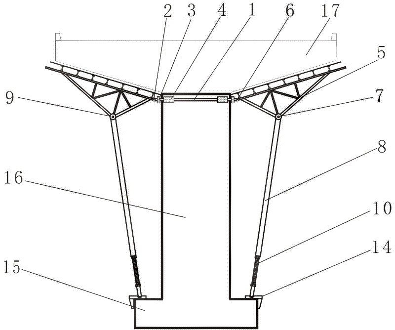
[0024] Type A: Cantilever braces for pouring a pier cap beam

[0025]It is composed of two pier-holding beams 1, a pair of tripod load-bearing joists 5, a pair of ball-end threaded diagonal braces 8, and a pair of ball-end bases 14; Clamp the pier 16 horizontally, and the clamp positioning pull rods respectively pass through the screw holes 3 at both ends of the two pier clamping beams, and are fixed by high-strength pull rod bolts, and fix the two pier clamping beams 1 on the upper end cover beam of the pier 16. Position: The rotatable connection hole 6 at the large acute angle end of the load-bearing joist of the tripod on the left side and the rotatable connection hole 2 set on the left end of the pier clamping beam are fixed by rotating bolts, and the rotatable connection at the obtuse angle end of the load-bearing joist of the tripod The hole 7 and the rotatable connection hole 9 at the top of the ball threaded diagonal strut 8 are fixed by rotating bolts, and the threa...

Embodiment 2

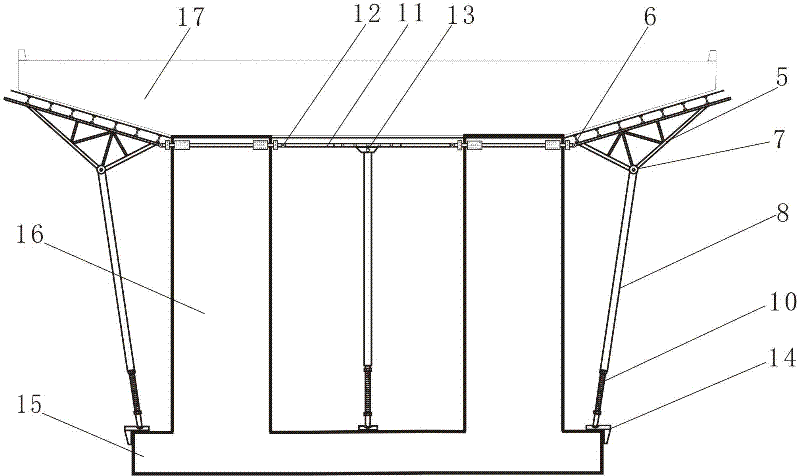
[0027] Type B: Cantilever braces for pouring two pier cap beams

[0028] The structure of this type of cantilever brace bracket is basically the same as that of Embodiment 1, the only difference being that in the case of two piers, the lower end of the cover beam 17 to be poured at the top of the central part of the two piers is provided with horizontal load-bearing joists 11 on the left and right, Horizontally support the steel formwork for the girder to be poured between the two piers; in the middle section of the horizontal load-bearing joist, there are vertically arranged ball-end threaded diagonal braces 8 to support the steel formwork for the girder to be poured between the two piers. The horizontal load-bearing joist 11 below the formwork; a ball base 14 is provided on the central bottom cap of the two piers to support the ball threaded diagonal brace 8;

[0029] Connecting holes 12 are provided on both ends of the horizontal load-bearing joist 11, length adjustment s...

Embodiment 3

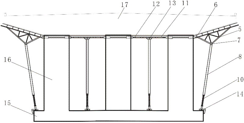
[0032] Type C: Cantilever braces for pouring three pier cap beams

[0033] The structure of this type of cantilever brace is basically the same as that of Embodiments 1 and 2, the only difference being that in the case of three piers, the lower end of the cover beam 17 to be poured between the middle pier and the top of the right pier is provided with Horizontal load-bearing joist 11, horizontally supports the steel formwork for the pouring cover beam between the middle pier and the right pier; in the middle section of the horizontal load-bearing girder, ball-threaded diagonal braces 8 are vertically arranged up and down to support the middle pier The horizontal load-bearing joist 11 under the steel formwork of the cap beam to be poured between the right pier and the right pier; a ball base 14 is provided on the central bottom cap of the middle pier and the right pier to support the ball threaded diagonal brace 8;

[0034] The cover beam cantilever diagonal bracing bracket o...


PUM


Abstract

The invention discloses a cantilever diagonal bracing bracket for casting a bridge pier cover beam. The cantilever diagonal bracing bracket is characterized by consisting of a pier clasping clamping beam, a tripod bearing joist, a bulb thread diagonal bracing rod and a bulb base; two ends of the pier clasping clamping beam are provided with rotatable connecting holes, clasping clamping positioning pull rod screw holes and friction clamping plates; the obtuse angle end and the big acute angle end of the tripod joist are provided with a rotatable connecting hole respectively; and two ends of a transverse bearing joist are provided with connecting holes, the lower end of the edge of the middle section of the transverse bearing joist is provided with a rotatable connecting hole, the top of the bulb thread diagonal bracing rod is provided with a rotatable connecting hole, a bulb thread screw is arranged at the bottom of the bulb thread diagonal bracing rod, and the bulb thread screw is arranged on the bulb base. By using the cantilever diagonal bracing bracket, a large amount of manual labor and steel tube supporting materials can be reduced, the construction benefit is improved, the construction progress of a bridge pier is quickened, the construction cost of engineering is reduced, and potential safety hazards are reduced; and the standard bracket has the advantages of factory production, mechanized hoisting, normalized construction and detachment and reuse.

Description

technical field [0001] The invention relates to a new method for supporting formwork used for pouring pier cover beams with a height of 3-15 meters in the construction of beam bridges, specifically a cantilever diagonal brace used for pouring pier cover beams. Background technique [0002] In the past, when pouring bridge pier cover beams and bridge slabs with a height of 3-15 meters, one is to use steel pipes to build full-frame support, and the other is to reserve steel rods on the pier for perforation to serve as support points for the cover beam. . The disadvantage of the former is that it requires a lot of labor to erect the steel pipe frame, which not only wastes time, but also requires a large amount of steel pipes as the main material, which greatly increases the construction cost; Repairing is carried out after the construction of the cap beam is completed, which not only affects the external appearance of the pier, but also increases the construction procedure. Th...

Claims


Application Information

Patent Timeline
Patent Type & Authority Applications(China)
IPC IPC(8): E01D21/00
Inventor 左孔海何双全李青洋
Owner SICHUAN CHUANJIAO ROAD & BRIDGE
Why Eureka
Try Eureka