A battery temperature sensing device and its preparation method
A technology of temperature sensing device and storage battery, which is applied in the direction of using electric devices, measuring devices, thermometers using electric/magnetic components directly sensitive to heat, etc., can solve the problems of low control accuracy and the like
- Summary
- Abstract
- Description
- Claims
- Application Information
AI Technical Summary
Problems solved by technology
Method used
Image
Examples
Embodiment 1
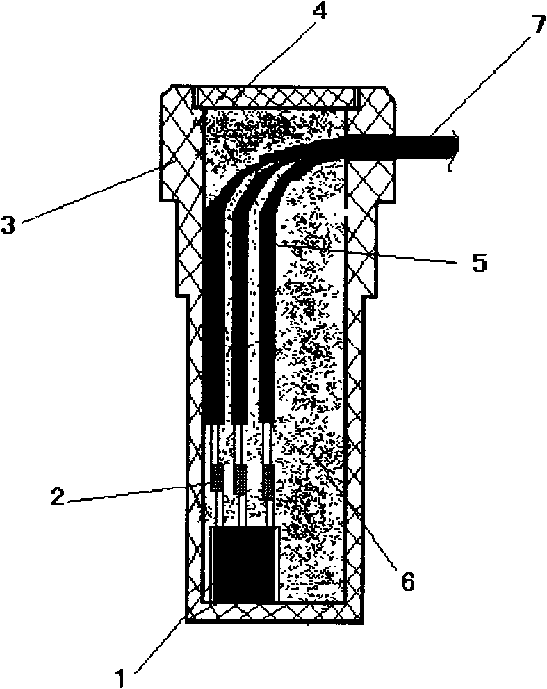
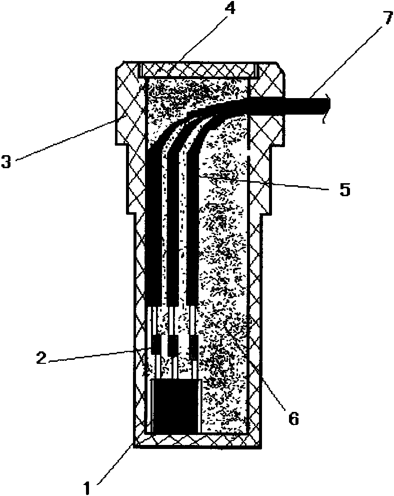
[0023] The battery temperature sensing device of this embodiment includes a housing 3, a cover 4, a wire 5, and a sensor chip 1. The sensor chip 1 is located at the bottom of the housing 3, and the upper end of the sensor chip 1 is provided with chip pins. The pin is welded with the wire 5 to form the chip pin and wire welding place 2; a part of the wire 5 passes through the temperature sensing device, and the part that passes through the temperature sensing device is provided with a heat shrink tube 7; the casing 3 is equipped with potting Material 6.
[0024] The bottom of the temperature sensing device is a cylinder, and the top is a hexagonal prism. The shell 3 is made of PVC polyvinyl chloride engineering plastic.
[0025] The sensor chip 1 is a DS18B20 digital temperature sensor, and the potting material includes epoxy resin, curing agent, thermal conductive material and filler.
[0026] The mass ratio of epoxy resin and curing agent is 7:3, epoxy resin is epoxy resin 618; cur...
Embodiment 2
[0035] The battery temperature sensing device of this embodiment includes a housing 3, a cover 4, a wire 5, and a sensor chip 1. The sensor chip 1 is located at the bottom of the housing 3, and the upper end of the sensor chip 1 is provided with chip pins. The pin is welded with the wire 5 to form the chip pin and wire welding place 2; a part of the wire 5 passes through the temperature sensing device, and the part that passes through the temperature sensing device is provided with a heat shrink tube 7; the casing 3 is equipped with potting Material 6.
[0036] The bottom of the temperature sensing device is a cylinder, and the top is a hexagonal prism. The shell 3 is made of PVC polyvinyl chloride engineering plastic.
[0037] The sensor chip 1 is a DS18B20 digital temperature sensor, and the potting material includes epoxy resin, curing agent, thermal conductive material and filler.
[0038] The mass ratio of epoxy resin and curing agent is 3:2, the epoxy resin is epoxy resin 618;...
Embodiment 3
[0050] The battery temperature sensing device of this embodiment includes a housing 3, a cover 4, a wire 5, and a sensor chip 1. The sensor chip 1 is located at the bottom of the housing 3, and the upper end of the sensor chip 1 is provided with chip pins. The pin is welded with the wire 5 to form the chip pin and wire welding place 2; a part of the wire 5 passes through the temperature sensing device, and the part that passes through the temperature sensing device is provided with a heat shrink tube 7; the casing 3 is equipped with potting Material 6.
[0051] The bottom of the temperature sensing device is a cylinder, and the top is a hexagonal prism. The shell 3 is made of PVC polyvinyl chloride engineering plastic.
[0052] The sensor chip 1 is a DS18B20 digital temperature sensor, and the potting material includes epoxy resin, curing agent, thermal conductive material and filler.
[0053] The mass ratio of epoxy resin and curing agent is 6:5, epoxy resin is epoxy resin 618; cur...
PUM
 Abstract
Description
Claims
Application Information
 - R&D
- Intellectual Property
- Life Sciences
- Materials
- Tech Scout
- Unparalleled Data Quality
- Higher Quality Content
- 60% Fewer Hallucinations
Browse by: Latest US Patents, China's latest patents, Technical Efficacy Thesaurus, Application Domain, Technology Topic, Popular Technical Reports.
© 2025 PatSnap. All rights reserved.Legal|Privacy policy|Modern Slavery Act Transparency Statement|Sitemap|About US| Contact US: help@patsnap.com


