Steel tube cooling device

A technology for cooling devices and steel pipes, which is applied in workpiece surface treatment equipment, metal rolling, manufacturing tools, etc. It can solve the problem of water entering the tail of steel pipes at running speeds, so as to eliminate the problem of water retention and reduce the phenomenon of water cutting , the effect of solving the problem of water retention

Active Publication Date: 2013-03-20
CISDI ENG CO LTD
View PDF6 Cites 0 Cited by
  • Summary
  • Abstract
  • Description
  • Claims
  • Application Information

AI Technical Summary

Problems solved by technology

Although the cooling method can effectively avoid the stagnation caused by water entering the head of the steel pipe to a certain extent, it cannot effectively solve the problem of water entering the tail of the steel pipe with a slower running speed.

Method used


Image

  • Steel tube cooling device
  • Steel tube cooling device
  • Steel tube cooling device

Examples


Embodiment Construction

[0027] The specific implementation manners of the present invention will be described in detail below in conjunction with the accompanying drawings.

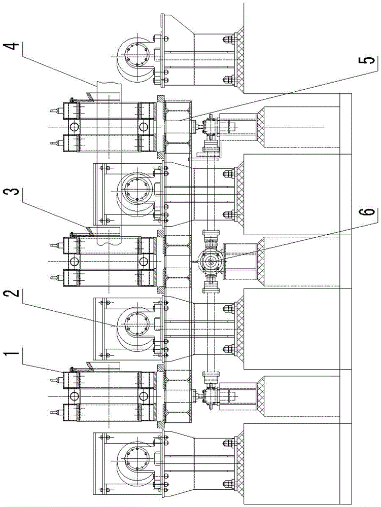
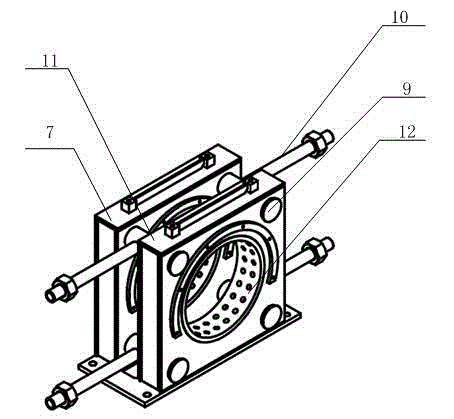
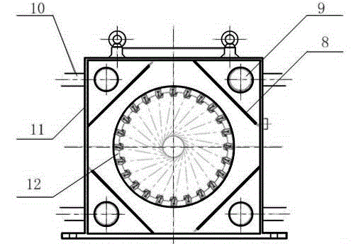
[0028] Such as Figure 1-3 As shown, it is a structural schematic diagram of an embodiment of the steel pipe cooling device of the present invention. The steel pipe cooling device of the present invention includes a plurality of cooling water tanks 1 respectively arranged between two adjacent conveying roller tables 2, and each cooling water tank 1 includes a The connecting water pipe 9 is connected in series and parallel to the sub-spray water tanks 7 and the water inlet pipe 10 connected with the connecting water pipe 9 and the external water supply pipe. The sub-spray box 7 includes an outer frame 11, a circular inner cavity 12 placed in the outer frame 11 and a nozzle 13 arranged on the inner peripheral wall of the circular inner cavity 12 along the circumferential direction of the circular inner cavity 12, the nozzle 13 Th...


PUM


Abstract

The invention discloses a steel tube cooling device which comprises cooling water tanks respectively arranged between two adjacent conveying rollers, wherein each of the cooling water tanks comprises subsidiary water injecting boxes and a water inlet pipe; the subsidiary water injecting boxes are serially connected with each other through a connecting water pipe and are parallel to each other; the water inlet pipe is connected to the connecting water pipe and an external water supply pipe; each of the subsidiary water injecting boxes comprises an outer frame, an inner circular cavity and nozzles; the inner circular cavity is arranged in the outer frame; the nozzles are distributed on the inner peripheral wall of the inner circular cavity along the periphery of the inner circular cavity; the water spraying directions of the nozzles are vertical to the axis of the inner circular cavity; and the distances between the extending lines of the water spraying directions of the nozzles and theaxis of the inner circular cavity are equal to each other and are less than or equal to the radius of a to-be-cooled steel tube. The steel tube cooling device provided by the invention can be used for greatly relieving and even eliminating the water retention problem of the head and tail parts of the steel tube in the running process of the steel tube. Clearances left between the serially connected subsidiary water injecting boxes can be used for solving the water storage problem of water sealing rings.

Description

technical field [0001] The invention relates to a cooling device, in particular to a cooling device for hot-rolled steel pipes. Background technique [0002] The traditional ERW welded pipe production technology of J55 steel grade oil pipe is firstly ERW high-frequency welding, weld heat treatment, and then flaw detection, wire processing, and delivery. However, due to the low production efficiency of this process, some welded pipe factories adopt the following process to increase production: connect the ERW welded pipe line, perform thermal tension reduction after induction heating, reheat sawing, and then go to the cooling bed, and finally manually deburr inspection library. Although this method greatly increases the output of welded pipes, due to the air cooling after reheating by electric induction and the low cooling rate, the final strength of the welded pipes is lower than that of the parent pipe. If you need to obtain higher strength steel pipes, or add alloy elemen...

Claims


Application Information

Patent Timeline
Patent Type & Authority Patents(China)
IPC IPC(8): B21B45/02B21B37/76
Inventor 韩会全方建忠
Owner CISDI ENG CO LTD
Why Eureka
Try Eureka