
Bicycle Lighting Device and DC Generator

A technology for lighting devices and alternators, which is applied to lighting devices, lighting device components, circuit devices, etc., can solve problems such as the inability to provide stable light, and achieve the effect of improving safety and visibility.

Inactive Publication Date: 2011-12-07
TRUMP TECH
View PDF2 Cites 2 Cited by
  • Summary
  • Abstract
  • Description
  • Claims
  • Application Information

AI Technical Summary

Problems solved by technology

[0006] The invention provides a bicycle lighting device and a direct current generator, which solves the problem that stable light cannot be provided in the prior art

Method used


Image

  • Bicycle Lighting Device and DC Generator
  • Bicycle Lighting Device and DC Generator
  • Bicycle Lighting Device and DC Generator

Examples


Embodiment Construction

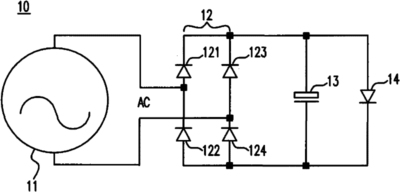
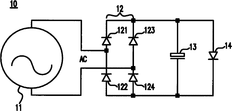
[0020] see figure 1 , which is a circuit diagram of the lighting device proposed by the present invention. The lighting device 10 includes a hub generator 11, which generates an alternating current AC. The hub generator 11 and a bridge rectifier 12 are connected in parallel. The bridge rectifier 12 includes four rectifier diodes 121, 122, 123, 124, and the bridge The type rectifier 12 is connected in parallel to an electric double-layer capacitor 13 (Electric Double-Layer Capacitor), or can be called a super capacitor (Ultracapacitor), and then connected to a light emitting diode 14.

[0021] The alternating current AC generated by the hub generator 11 will form a direct current after passing through the bridge rectifier 12 . However, the voltage of the direct current will still change with time. Therefore, if you want to keep the light-emitting diode 14 in a constant bright state when it is powered on, you need to use the electronic double layer capacitor 13 as in the presen...


PUM


Abstract

The present invention proposes a bicycle lighting device and a DC generator. The lighting device includes an AC generator; a rectifier connected in parallel with the AC generator; an electronic double-layer capacitor connected in parallel with the rectifier; and a light emitting body, which is connected in parallel with the electronic double layer capacitor, wherein when the alternator is running, it charges the electronic double layer capacitor, and when the light voltage drops, the electronic double layer capacitor discharges to maintain the voltage at least 1 volt.

Description

technical field [0001] The present invention relates to a bicycle lighting device and a DC generator, and in particular, to a constant brightness lighting device and a hub DC generator for a bicycle. Background technique [0002] Currently, there are two types of small lighting devices installed on bicycles. One is to be equipped with a battery itself to supply the power for lighting, and the other is to provide the required power through the small generator that already has on the bicycle. [0003] The hub dynamo (Hub Dynamo), or hub dynamo, is a small dynamo specially used in bicycles. Its size is very small, so it can be directly installed on the bicycle to serve as a power supply for car lights. source of electricity. When the bicycle is moving, the rotation of the axle will drive the rotation of the hub generator to generate electricity, and the electricity will be directly output to the lighting device. In this way, the lighting device will not need to constantly rep...

Claims


Application Information

Patent Timeline
IPC IPC(8): F21S9/04F21V23/00H02J7/14F21W111/02F21Y101/02
Inventor 黄奕忠洪建平
Owner TRUMP TECH
Learn More