
Device and method for generating stimulated Brillouin scattering in front of continuous pumping beam combiner

A technology of stimulated Brillouin and generation device, applied in the field of photoelectron detection, can solve the problems of increased cost, complex structure, and reduced energy of two laser beams, etc.

Active Publication Date: 2011-12-07
NANCHANG HANGKONG UNIVERSITY
View PDF3 Cites 13 Cited by
  • Summary
  • Abstract
  • Description
  • Claims
  • Application Information

AI Technical Summary

Problems solved by technology

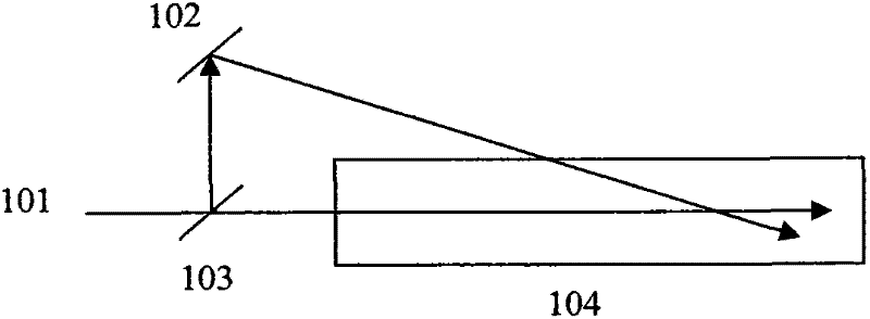
attached figure 1 And attached figure 2 All shown are cases of crossover setups with figure 1 In the process, two mirrors 102 and 103 are used to split a beam of laser light 101 into two beams, and then the separated two beams of laser light intersect in a stimulated Brillouin scattering medium 104 to generate stimulated Brillouin scattering light In this device, since one laser beam is divided into two beams, the frequency and polarization state of the two laser beams are exactly the same. The structure of the device is simple, but there are two problems. One problem is Since one laser beam is divided into two beams, the energy of the two laser beams must not be very high. The second problem is that the interaction distance between the two beams is very short due to the intersection method. , resulting in insufficient utilization of the laser beam
attached figure 2 It shows another way of intersecting setting. In order to improve the problem of dividing one laser beam into two beams and causing each energy to become smaller, it is proposed to use the beams emitted by two lasers 201 for intersecting incidence by means of a mirror 202 To the stimulated Brillouin scattering medium 203, each of them is an independent laser, so the energy will not become smaller. In order to ensure that the laser light emitted by the two lasers is exactly the same in nature to ensure the occurrence of stimulated amplification, The same seed laser needs to be injected into the two lasers respectively. In this way, although the system solves the problem of reducing the energy of the laser beam, the device still cannot solve the problem of short interaction distance
In order to solve the problem of short interaction distance, the best way is to overlap the optical paths of the two laser beams. In the existing optical path overlapping settings, as disclosed in the published Chinese patent application CN101266342A, in order to realize the two The pulsed laser beams are overlapped on one optical path with a time difference (which is required for secondary stimulated Brillouin amplification). The device uses photoelectric crystals to control the two laser beams with different polarization states, so as to ensure both The two pulsed lasers are coupled to one optical path with a time difference, and the same polarization state can be guaranteed when reaching the stimulated Brillouin scattering medium. In this device, a polarization coupling mirror and an electro-optic crystal are required to realize the front and rear two beams. The polarization state control of laser beams is not only complicated in structure, but also requires high requirements for electro-optic crystals, and is accompanied by the following problems. The two laser beams used in this device either divide one laser beam into two beams, so that It will lead to the reduction of the energy of the two laser beams. If the two laser beams generated by two lasers are used, although the energy intensity is kept from being reduced, the use of two lasers will take up more space correspondingly, because Two lasers obviously need to occupy twice as much space, and the space problem cannot be solved or it is very difficult to solve in many cases, or it will cause a rapid increase in cost

Method used


Image

  • Device and method for generating stimulated Brillouin scattering in front of continuous pumping beam combiner
  • Device and method for generating stimulated Brillouin scattering in front of continuous pumping beam combiner
  • Device and method for generating stimulated Brillouin scattering in front of continuous pumping beam combiner

Examples


Embodiment Construction

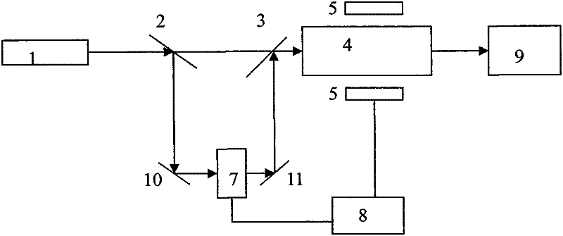
[0011] Attached below image 3 To illustrate the first embodiment of the present invention, the seed laser (1) sends a seed laser, which is transmitted to the beam splitter 2, and then split into two beams, wherein the first beam of seed laser continues to propagate forward along the original direction to reach the combined beam. The beam mirror 3, after passing through the beam combiner 3, is incident on the laser amplification medium 4 behind the beam combiner 3, and the second beam of seed laser is reflected and transmitted to the first total reflection mirror 10, and is reflected by the first total reflection mirror 10 Then it is incident on the optical path delay device 7, and after passing through the delay adjustment device, it is reflected by the second total reflection mirror 11 and then incident on the beam combining mirror 3, and the beam combining mirror 3 overlaps the light beam with the first beam of seed laser beam optical path Reflected in a way to make it inci...


PUM


Abstract

The invention discloses a simulated Brillouin scattering generating device with a preposed continuously pumping beam combiner and a simulated Brillouin scattering generating method. The simulated Brillouin scattering generating device comprises a pulse seed laser apparatus (1), a beam splitter (2), a beam combiner (3), a laser amplifying medium (4), a light path delay adjusting device (7), a first holophote 10 and a second holophote 11, a laser amplifying medium pumping system (5), a controller 8 and a simulated Brillouin scattering medium 9.

Description

technical field [0001] The invention relates to a Brillouin scattering laser device, which belongs to the technical field of photoelectron detection. Background technique [0002] At present, the technology of underwater target detection using Brillouin scattering has been practically applied. One of the biggest challenges in the development of this technology is the problem of detection distance. As we all know, the visible light window of fresh water or sea water is around 532nm, but even with this The wavelength of the laser is used as the laser wavelength for Brillouin scattering underwater detection. Due to the different water quality of the sea or lakes to be detected in practice, especially with the intensification of environmental pollution in recent years, there are generally poor water quality in various waters and poor water quality. The direct impact of laser underwater detection is that it seriously affects the transmission distance of the laser. Even in unpollu...

Claims


Application Information

Patent Timeline
IPC IPC(8): G02F1/35
Inventor 何兴道史久林刘娟李淑静陈学岗陈蔚
Owner NANCHANG HANGKONG UNIVERSITY
Learn More