Utility-scale osmotic grid storage
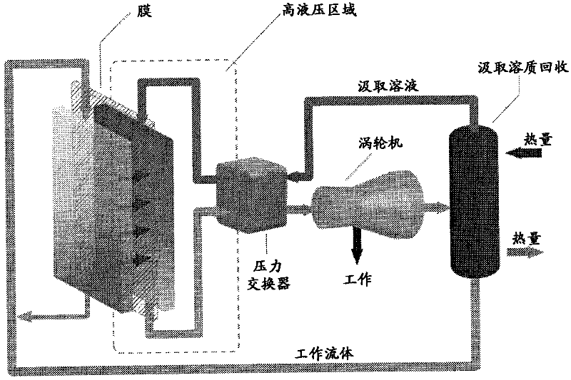
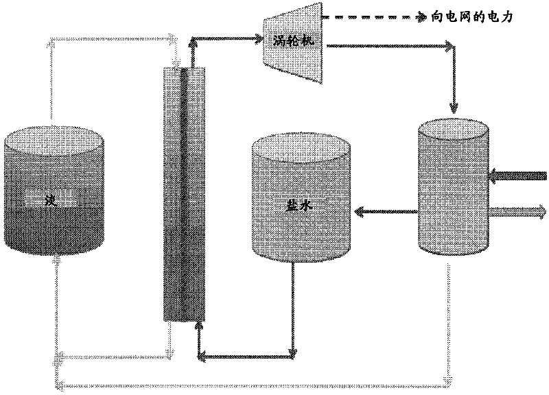
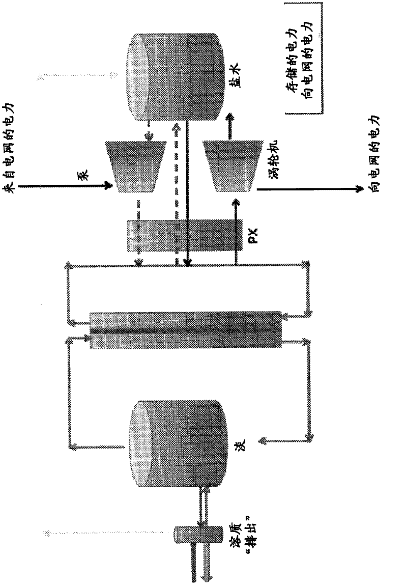
A power and battery technology, applied in the field of practical-scale power grid storage, can solve the problem of no large-scale power storage options
- Summary
- Abstract
- Description
- Claims
- Application Information
AI Technical Summary
Problems solved by technology
Method used
Image
Examples
Embodiment 1
[0067] Simulate various storage technologies, including the disclosed infiltration system and method, based on comparative dimensions and operating parameters, and evaluate in terms of efficiency and capital cost. Table 1 below summarizes the results regarding efficiency.
[0068] Table 1
[0069] Storage technology
effectiveness
Pumped storage
70-85%
75-85%
Na-S battery
85-90%
Li-ion battery
90-95%
70-80%
Energy storage wheel
90-95%
Infiltration system
75-85%
[0070] As shown in the table, the efficiency of the disclosed infiltration system and method is competitive, especially in view of the fact that waste heat can be used.
[0071] The evaluation results also show that the infiltration system and method disclosed herein have a lower capital cost per kilowatt than conventional storage technologies. For example, pumped storage systems are 2 to 4 times more expensive. Flow batteries are up to 3 times more expensive. Sodium-...
Embodiment 2
[0074] A cost analysis is performed on the penetration grid storage system simulated according to one or more embodiments disclosed herein. The system specifications on which the simulation is based include a total energy storage capacity of 600MWH, a transmission power of 100MW, a transmission time of 12 hours, a pressure of 150ATM, and a 1GW thermal power plant used to provide waste heat. The analysis yielded an estimated cost of $0.08 per kWh, indicating the feasibility of penetrating grid storage as an energy solution.
Embodiment 3
[0076] An analysis was performed to simulate the cost per kilowatt hour as a function of the storage capacity of the penetration grid storage system according to various embodiments. The results are shown in Table 2 below, indicating that the cost per kilowatt-hour decreases with increasing MWH storage capacity. Storage has tripled and costs have been reduced by more than half. Compared to conventional grid storage options, the estimated $0.098 / KWH under 30MWH storage capacity is attractive.
[0077] Table 2
[0078]
PUM
 Abstract
Description
Claims
Application Information
 - R&D
- Intellectual Property
- Life Sciences
- Materials
- Tech Scout
- Unparalleled Data Quality
- Higher Quality Content
- 60% Fewer Hallucinations
Browse by: Latest US Patents, China's latest patents, Technical Efficacy Thesaurus, Application Domain, Technology Topic, Popular Technical Reports.
© 2025 PatSnap. All rights reserved.Legal|Privacy policy|Modern Slavery Act Transparency Statement|Sitemap|About US| Contact US: help@patsnap.com


