A fan-shaped door mechanism and its application driving mechanism

A driving mechanism and fan-shaped door technology, which is applied to the control mechanism, power control mechanism, turnstile and other directions of the wing fan, can solve the problems of high requirements, increased assembly workload and difficulty, and unfavorable repair and maintenance.

Inactive Publication Date: 2011-12-14
张俊明
View PDF7 Cites 14 Cited by
  • Summary
  • Abstract
  • Description
  • Claims
  • Application Information

AI Technical Summary

Problems solved by technology

The disadvantages are: the upper and lower gears need to occupy space outside the swing rod of the door, which is not conducive to the closeness of the left and right doors in the gate to the center line; the mechanism for the transmission of the upper gear to the inner door is complicated to assemble, which is not conducive to repair and maintenance; the inner and outer doors must be It can only be integrated when it is assembled to the door swing rod, which increases the workload and difficulty of assembly
[0003] Another Chinese patent with application number 200620040707.6 discloses a fan door mechanism in a fan door gate machine. The middle of the door swing rod saves the space other than the swing

Method used


Image

  • A fan-shaped door mechanism and its application driving mechanism
  • A fan-shaped door mechanism and its application driving mechanism
  • A fan-shaped door mechanism and its application driving mechanism

Examples


Embodiment Construction

[0028] In order to make the object, technical solution and advantages of the present invention clearer, the present invention will be further described in detail below in conjunction with the accompanying drawings and embodiments. It should be understood that the specific embodiments described here are only used to explain the present invention, not to limit the present invention.

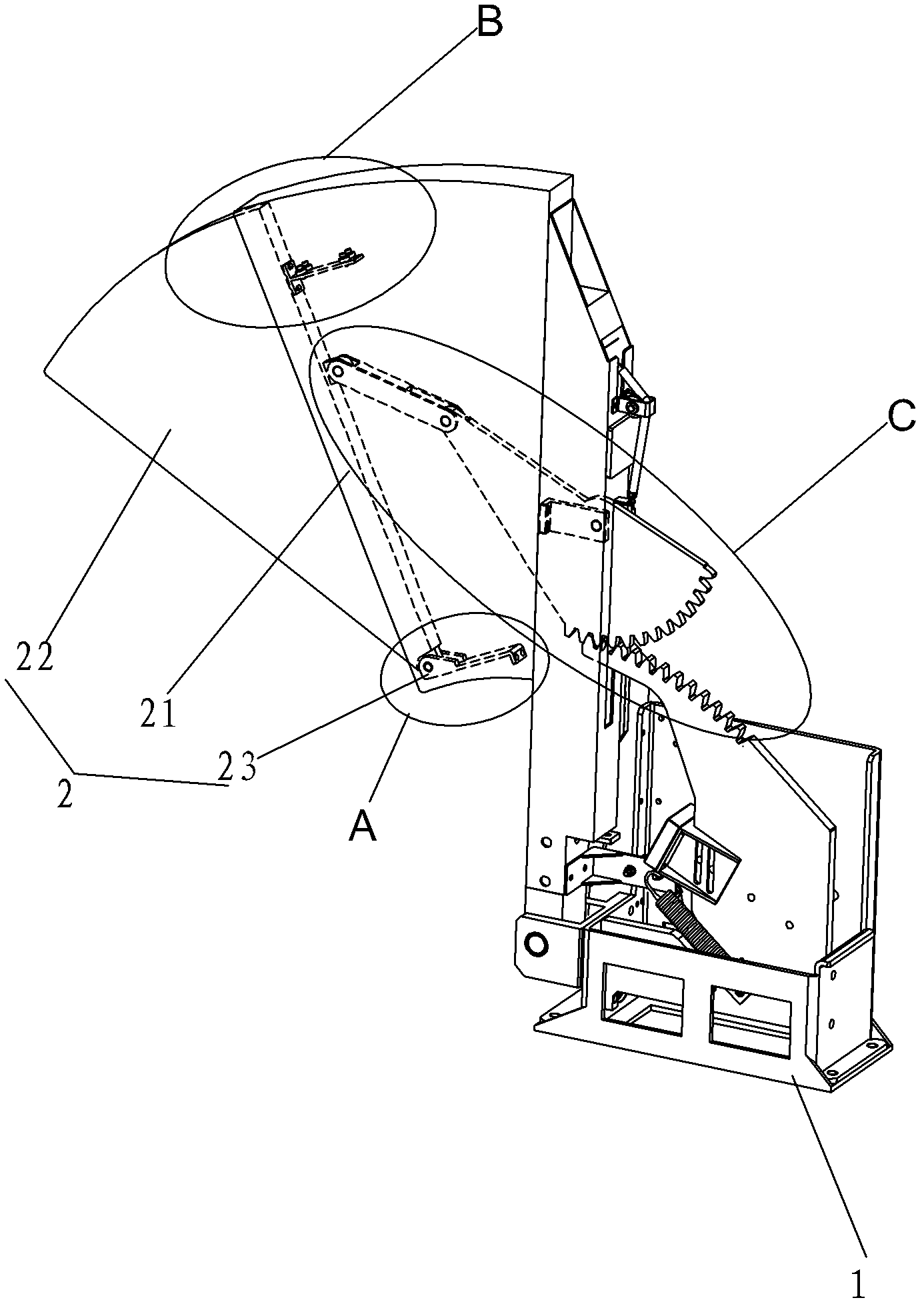
[0029] refer to figure 1 As shown, the present invention discloses a fan-shaped door structure, which includes a base 1, a fan-shaped door 2, a gear assembly 3 and a fan-shaped door linkage assembly 4, wherein:

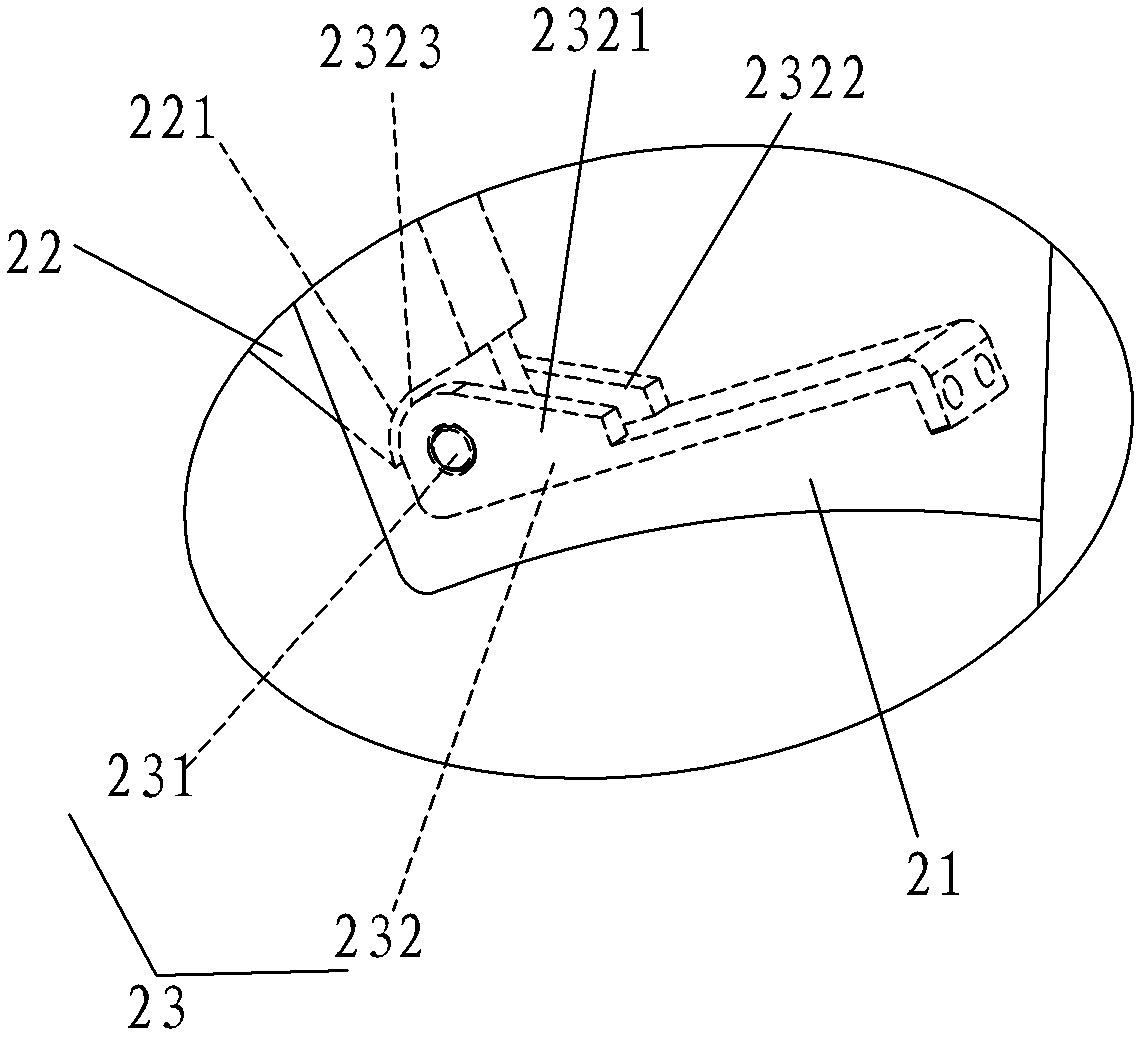
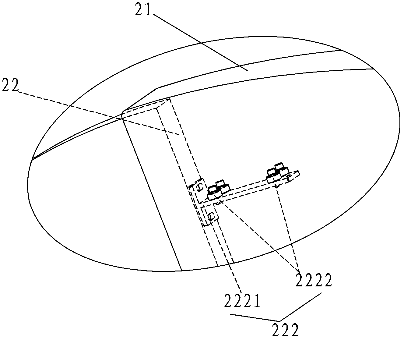
[0030] Cooperate Figure 1A , 5 , 5D, and 5E, the fan-shaped door 2 includes an outer door 21, an inner door 22 and a connecting assembly 23. There is an empty shell in the outer door 21, and the inner door 22 can be movably sleeved on the outer door 23 through the connecting assembly. In the door 21; the connecting assembly 23 includes a connecting shaft 231 and a rotating shaft seat 2...


PUM


Abstract

The invention discloses a fan-shaped door mechanism and its driving mechanism. The fan-shaped door mechanism has a base, a fan-shaped door arranged on the base, a gear assembly and a fan-shaped door connecting rod assembly. The fan-shaped door includes an outer door, an inner door and connecting Assemblies, the inner door is movably nested with the outer door through the connecting assembly; the gear assembly includes the upper gear, the lower gear and the upper gear connection assembly, the upper gear is movably connected with the outer door through the upper gear connection assembly, and the upper gear and the lower gear are connected to each other. meshing; one end of the fan-shaped door connecting rod is connected with the upper gear, and the other end is connected with the inner leaf door, and the inner leaf door enters and exits in the outer leaf door under the action of the fan-shaped door connecting rod assembly. The invention has simple structure, easy assembly, high production efficiency, does not occupy space other than the swing rod, improves the overall aesthetics of the gate unit, and enables the movement to be used in various gates; maintains the structure of the swing rod root It is not damaged, which ensures the stability of the important part of the movement structure - the swing rod.

Description

technical field [0001] The invention relates to the technical field of a gate for a rail transit automatic ticketing system, in particular to a fan-shaped door mechanism and its applied driving mechanism and gate. Background technique [0002] In the application of gates in rail transit (subway, railway, etc.) automatic fare collection systems, in order to install the gate mechanism that can effectively block wider passages in the narrow gate body, the industry generally adopts the design of the gate mechanism into the practice of telescopic doors. The current retractable inner door drive mechanism, one of which is the Chinese patent application No. 200710047469.0, which discloses a wide channel scissor door device for self-supporting ticket checking machines. At the same time, the lower gear, the upper gear and the linkage mechanism to promote the inner door. The advantage of such design is, the stability of leaf door swing bar is good, and the volume of the upper gear th...

Claims


Application Information

Patent Timeline
IPC IPC(8): E01F13/06E06B11/08E05F15/12E05F15/611
Inventor 张俊明
Owner 张俊明
Why Eureka
Try Eureka