A controllable gas spring

A gas spring, hollow piston rod technology, applied in springs, springs/shock absorbers, shock absorbers, etc., can solve the problems of low efficiency and many process steps, and achieve the effect of saving space, reducing costs and saving materials

Inactive Publication Date: 2011-12-14
扬州市明瑞气弹簧有限公司
View PDF6 Cites 5 Cited by
  • Summary
  • Abstract
  • Description
  • Claims
  • Application Information

AI Technical Summary

Problems solved by technology

It has many process steps and low efficiency

Method used


Image

  • A controllable gas spring
  • A controllable gas spring
  • A controllable gas spring

Examples


Embodiment Construction

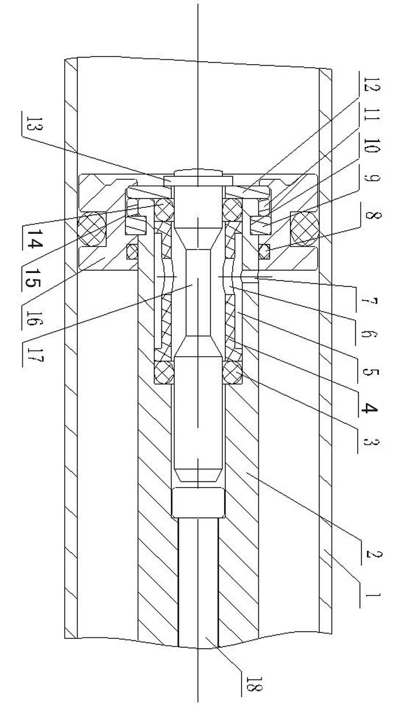
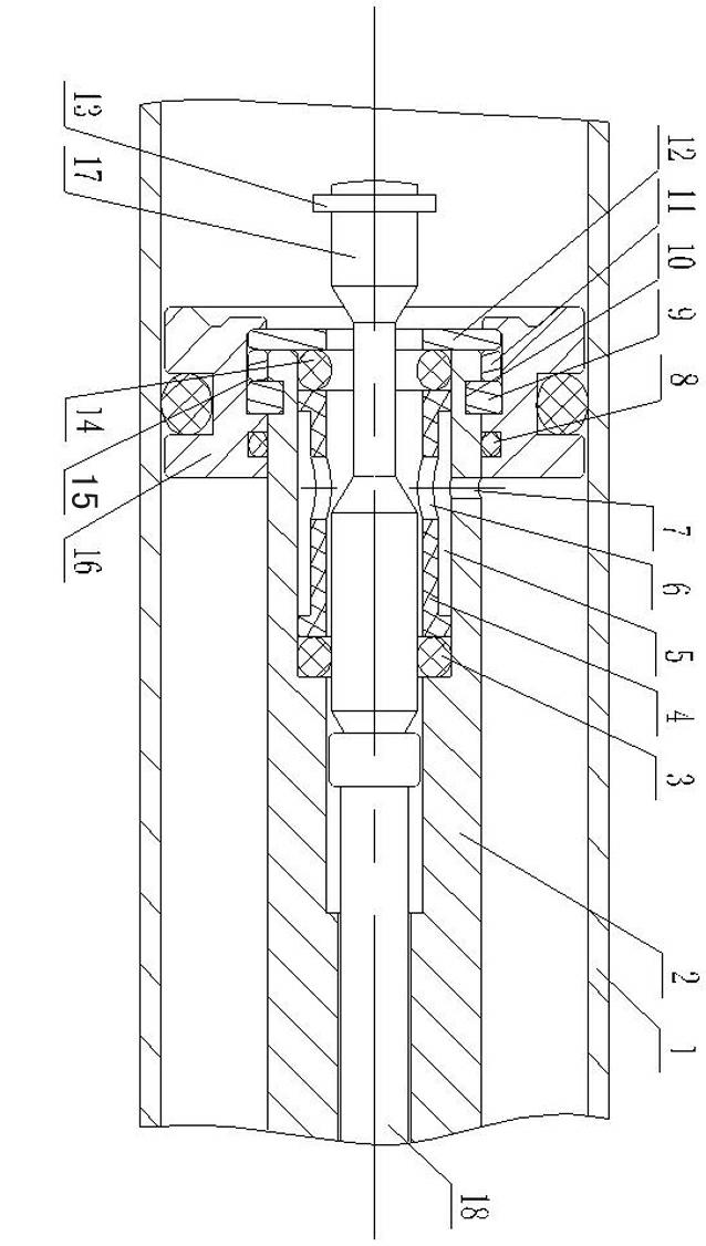
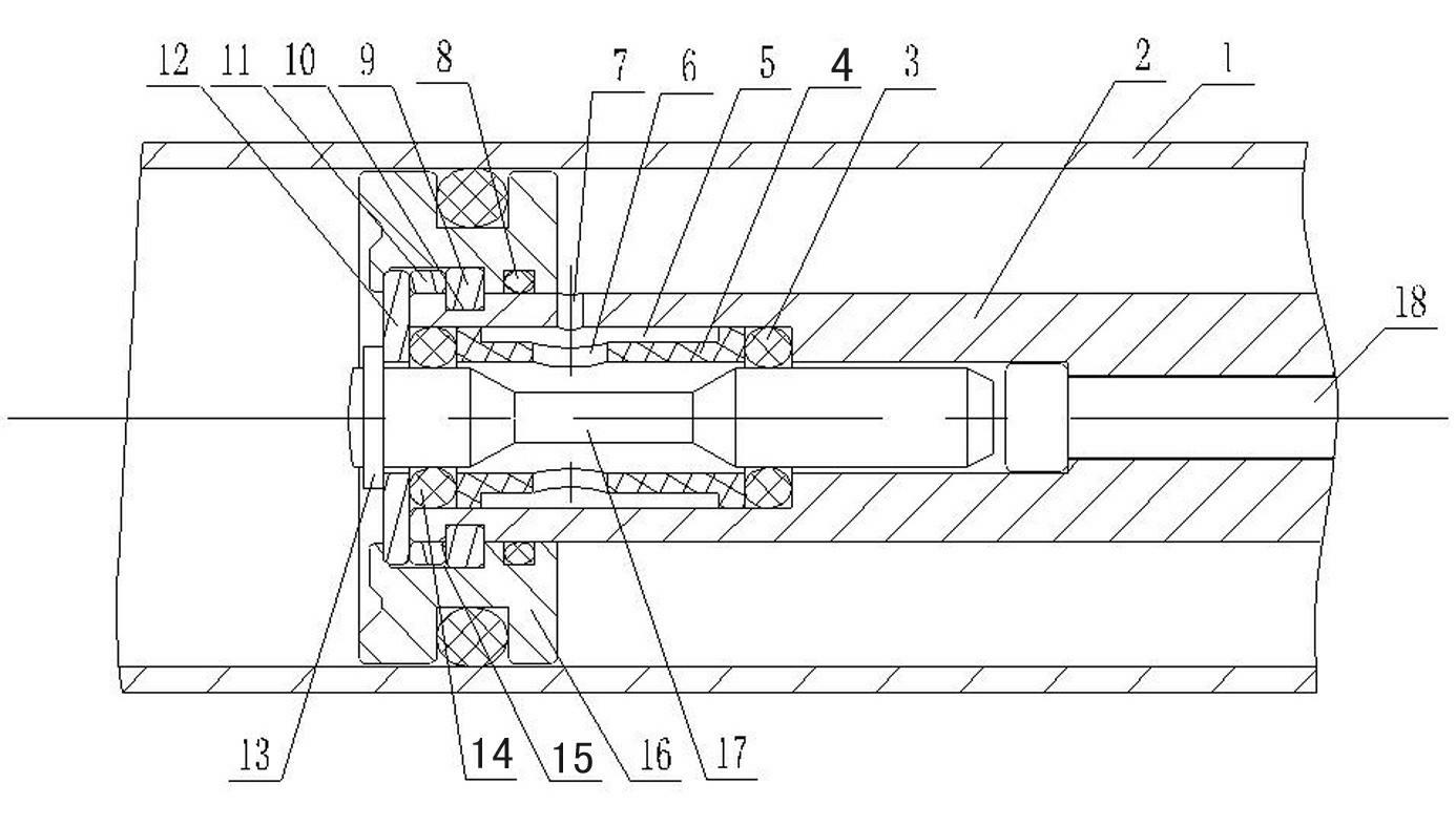
[0010] Such as figure 1 , 2 As shown, it is a controllable gas spring, including a cylinder 1, a piston 16, a hollow piston rod 2, a valve needle 17 and a return rod 18, the piston 16 is arranged in the cylinder 1, and the rear end of the hollow piston rod 2 Inserted in the piston 16 , the valve needle 17 and the return rod 18 are respectively inserted in the hollow piston rod 2 , and the return rod 18 is arranged on the front side of the valve needle 17 .

[0011] A first seal 8 is arranged between the piston 16 and the hollow piston rod 2, a first groove 15 is arranged radially at the rear end of the piston 16, and an annular second groove 10 is arranged radially outside the rear end of the hollow piston rod 2, the hollow Two arc collars 9 and a gasket 11 are arranged in the first groove 15 between the piston rod 2 and the piston 16, and the two arc collars 9 are respectively arranged in the second groove 10, and the gasket 11 is arranged On the rear side of the arc collar...


PUM


Abstract

A controllable gas spring, relating to the structure of the gas spring, including a cylinder, a piston, a hollow piston rod and a valve needle, a first through hole is arranged radially on the hollow piston rod outside the piston, and a hole is arranged between the piston and the hollow piston rod For the first seal, the rear end of the piston is radially provided with a first groove, and a pressure riveting gasket is arranged in the first groove, and a limit step is arranged on the valve needle outside the hollow piston rod, and the outer diameter of the rear end of the hollow piston rod is An annular second groove is arranged in the direction, and two arc-shaped collars are arranged in the first groove between the hollow piston rod and the piston, and the two arc-shaped collars are respectively arranged in the second groove; the rear end of the hollow piston rod A third groove connected to the first through hole is arranged inside, and a second seal, a bushing and a third seal are arranged in sequence between the hollow piston rod and the valve needle in the third groove, and the bushing A second through hole communicating with the third groove is arranged radially on the upper side, and the third sealing member is arranged on the front side of the pressure riveting gasket. The invention reduces processing difficulty.

Description

technical field [0001] The invention relates to the fields of a spring, a shock absorber and a shock absorber, in particular to the structure of a gas spring. Background technique [0002] Gas spring is an accessory that can support, buffer, brake, height adjust and angle adjust. It is widely used in medical equipment, automobile, furniture, textile equipment, machinery manufacturing and other fields. The principle is to fill the closed cylinder with an inert gas or an oil-gas mixture, so that the pressure in the cavity is several times or dozens of times higher than the atmospheric pressure, and the pressure difference generated by the cross-sectional area of ​​the piston rod is smaller than that of the piston. To realize the movement of the piston rod. At present, the controllable gas spring is connected with the piston (controllable valve) and the piston rod by pressure riveting. The requirements for concentricity at the same time make the piston and piston rod require ...

Claims


Application Information

Patent Timeline
Patent Type & Authority Applications(China)
IPC IPC(8): F16F9/32F16F9/36
Inventor 桂万水
Owner 扬州市明瑞气弹簧有限公司
Why Eureka
Try Eureka