A built-in level gauge for indicating the level of liquid in equipment or containers

A liquid level gauge, built-in technology, applied in the direction of the buoy liquid level indicator, etc., can solve the problems of clutter, steam or electric energy consumption, and achieve the effect of neat appearance, avoiding oil leakage, and no wearing parts

Inactive Publication Date: 2011-12-14
CHINA PETROLEUM & CHEM CORP
View PDF6 Cites 5 Cited by
  • Summary
  • Abstract
  • Description
  • Claims
  • Application Information

AI Technical Summary

Problems solved by technology

Therefore, the equipment site appears messy and co

Method used


Image

  • A built-in level gauge for indicating the level of liquid in equipment or containers
  • A built-in level gauge for indicating the level of liquid in equipment or containers
  • A built-in level gauge for indicating the level of liquid in equipment or containers

Examples


Embodiment Construction

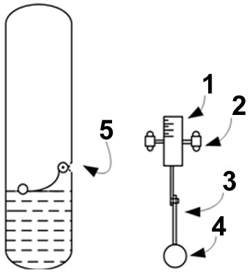
[0018] The liquid level gauge of the present invention is made of floating ball 4, telescopic fixed connecting rod 3, rotating dial 1, bearing support 2 and visible convex lens 5 installed on the container, as image 3 shown. Install the visible convex lens at the proper position of the container, and install the rotating dial through the bearing bracket at the center level of the visible convex lens inside the container. There are threaded holes on the bearing bracket to cooperate with the bolts on the container wall, or directly weld the bracket on the container wall. Then the floating ball is connected with the rotary dial through the telescopic fixed connecting rod, so far a complete built-in liquid level gauge is installed. When the floating ball moves up and down with the liquid level, the floating ball also drives the rotating dial to rotate through the connecting rod. The operator can easily observe the value on the rotating dial through the visible convex lens instal...


PUM


Abstract

The liquid level gauge of the present invention is composed of a floating ball 4, a telescopic fixed connecting rod 3, a rotating dial 1, a bearing bracket 2 and a visible convex lens 5 installed on the container. Install the visible convex lens at the proper position of the container, install the rotating dial through the bearing bracket at the center level of the visible convex lens inside the container, and then connect the floating ball and the rotating dial through a telescopic fixed link, so far a complete built-in The liquid level gauge is installed. When the floating ball moves up and down with the liquid level, the floating ball also drives the rotating dial to rotate through the connecting rod. The operator can easily observe the value on the rotating dial through the visible convex lens installed on the container, and then know the liquid level. high. Since the entire liquid level gauge is in the equipment container, the problem of freezing and blocking of conventional glass tube level gauges and magnetic column level gauges is eliminated.

Description

technical field [0001] The invention relates to an on-site indicating liquid level gauge commonly used in industrial production, which is especially suitable for indicating the liquid level of a water tank and the water level in an air cooling tower and a water cooling tower in an air separation device. Background technique [0002] In industrial production, it is often necessary to measure and control the liquid level of some equipment and containers. There are two main purposes of liquid level measurement: one is to ensure the quantity of raw materials, semi-finished products or finished products in the container through liquid level measurement, so as to ensure the continuous supply of materials required in each link of production or to carry out economic accounting; the other is to pass Liquid level measurement, to know whether the liquid level is within the specified range, so that the production can be carried out normally, so as to ensure the quality, output and safe ...

Claims


Application Information

Patent Timeline
IPC IPC(8): G01F23/34
Inventor 常兴路
Owner CHINA PETROLEUM & CHEM CORP
Why Eureka
Try Eureka