Ammonia-burning internal combustion engine

A technology for internal combustion engines and fuels, which can be applied to combustion engines, internal combustion piston engines, liquid fuel feeders, etc., and can solve problems such as the aggravation of the global warming effect

Inactive Publication Date: 2011-12-14
TOYOTA JIDOSHA KK +1
View PDF6 Cites 7 Cited by
  • Summary
  • Abstract
  • Description
  • Claims
  • Application Information

AI Technical Summary

Problems solved by technology

However, in this case, if the fuel is combusted, CO will be generated that will aggravate the global warming effect. 2

Method used


Image

  • Ammonia-burning internal combustion engine
  • Ammonia-burning internal combustion engine
  • Ammonia-burning internal combustion engine

Examples


Embodiment Construction

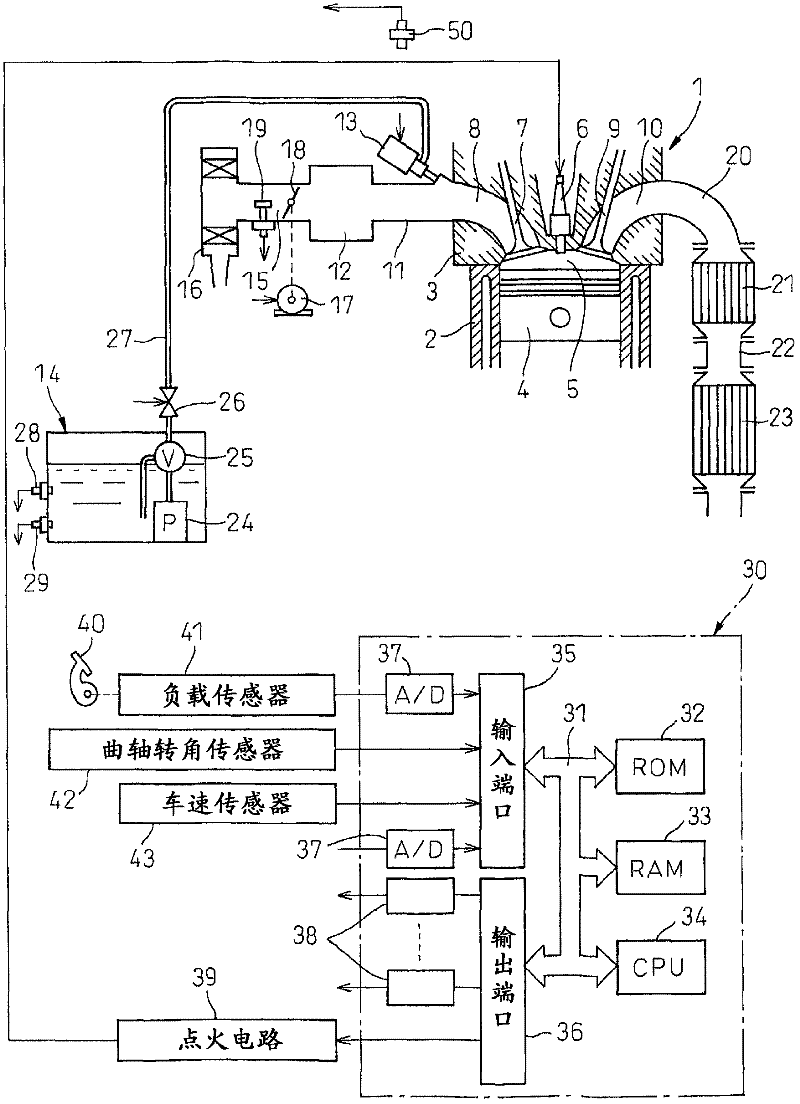
[0031] refer to figure 1 , 1 represents the main body of the internal combustion engine, 2 represents the cylinder block, 3 represents the cylinder head, 4 represents the piston, 5 represents the combustion chamber, 6 represents the plasma flow spark plug arranged at the center of the top surface of the combustion chamber 5 and emits the plasma flow, 7 represents the intake air Valve, 8 represents the intake port, 9 represents the exhaust valve, and 10 represents the exhaust port. The intake port 8 is connected to a balance box 12 via an intake branch pipe 11 , and each intake manifold 11 is provided with a liquid ammonia injection valve 13 for injecting liquid ammonia into the corresponding intake port 8 . Liquid ammonia is supplied from the fuel tank 14 to the liquid ammonia injection valve 13 .

[0032] The balance box 12 is connected to an air filter 16 via an intake duct 15, and a throttle valve (throttle valve) 18 driven by an actuator (actuator) 17 and intake air using...


PUM


Abstract

Inside an engine compartment (53) of a vehicle, an ammonia concentration sensor (50) is arranged above a liquid ammonia injector (13) which is attached to an internal combustion engine body (1) and to the rear in a direction of progression of the vehicle. An ammonia concentration which is detected by the ammonia concentration sensor (50) is used as the basis to judge if ammonia is leaked.

Description

technical field [0001] The present invention relates to internal combustion engines burning ammonia. Background technique [0002] Conventionally, fossil fuels have been mainly used as fuel in internal combustion engines. However, in this case, if the fuel is combusted, CO will be generated that will aggravate the global warming effect. 2 . On the other hand, when ammonia is burned, CO is not produced at all 2 , therefore, it is known that in order not to generate CO 2 On the other hand, an internal combustion engine using ammonia as a fuel (refer to Patent Document 1). [0003] Patent Document 1: Japanese Patent Application Laid-Open No. 5-332152 Contents of the invention [0004] Ammonia has a bad smell, so when ammonia is used as fuel, some countermeasures should be taken against leakage of ammonia. However, in the internal combustion engine described above, no consideration is given to leakage of ammonia. [0005] Therefore, in the present invention, in an ammon...

Claims


Application Information

Patent Timeline
Patent Type & Authority Applications(China)
IPC IPC(8): F02M37/00F02D45/00
CPCF02M2200/18F02M21/0224Y02T10/40F02M25/022F01N2570/18F02M21/0278F02M21/0287F02D41/0025F02D41/221F02M21/0293F02D19/029F02B43/10F02D19/025F01N2560/021F02M37/0029F02D19/027Y02T10/32F01N3/0814F02M21/0206F02M2037/087F02M25/0809F02D2041/1468F02M37/10F02B2201/02F02M25/0224F02M25/0227F02M25/028Y02T10/30F02D45/00F02M37/00F02M61/16
Inventor 小岛进清水里欧杉本知士郎道川内亮菊田光石井和德辻野睦青木恒明武田启壮
Owner TOYOTA JIDOSHA KK
Why Eureka
Try Eureka