A floor rail type highly integrated intelligent iron driller

A highly integrated, iron driller technology, applied in drill pipes, drill pipes, drilling equipment, etc., can solve the problems of easy fatigue damage of springs, poor integration of iron drillers, low degree of automation, etc., to improve work efficiency and increase The effect of equipment life and high degree of automation

Inactive Publication Date: 2011-12-21
金华萨博思石油机械有限公司
View PDF8 Cites 19 Cited by
  • Summary
  • Abstract
  • Description
  • Claims
  • Application Information

AI Technical Summary

Problems solved by technology

When the spinner is working, it needs to overcome the spring force, and the release of the stored energy of the spring after work will also cause impact on the equipment, and the spring is easy to fatigue and damage
Moreover, the integration of the entire iron driller is poor, the main and back pliers are separated, and the degree of automation is low. Generally, at least two workers are required for on-site operation.

Method used


Image

  • A floor rail type highly integrated intelligent iron driller
  • A floor rail type highly integrated intelligent iron driller
  • A floor rail type highly integrated intelligent iron driller

Examples


Embodiment 1

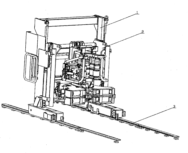
[0022] Example 1: Combining Figure 1-Figure 12, the present invention is a floor track type highly integrated intelligent iron driller, which is composed of a lift car (1), a clamp head frame (2), and a guide rail (3), and the lift car (1) is on the guide rail (3) Move, the upper part of the clamp head frame (2) is articulated on the lift truck (1), and the lower part of the clamp head frame (2) is connected with the lift truck (1) through a shackle (4), and the lift truck (1) is composed of left and right The two side frames are composed of crossbeams, and the left and right side frames are respectively installed on two guide rails (3). The lift car (1) drives the transmission gear (102) to rotate through the lift car hydraulic motor (130) to realize the movement on the guide rail (3). Move up, the front positioning plate (131) welded on the front and rear plates of the foot box, the rear positioning plate (126) and the baffle plate (129) connected by bolts on the inner plat...

Embodiment 2

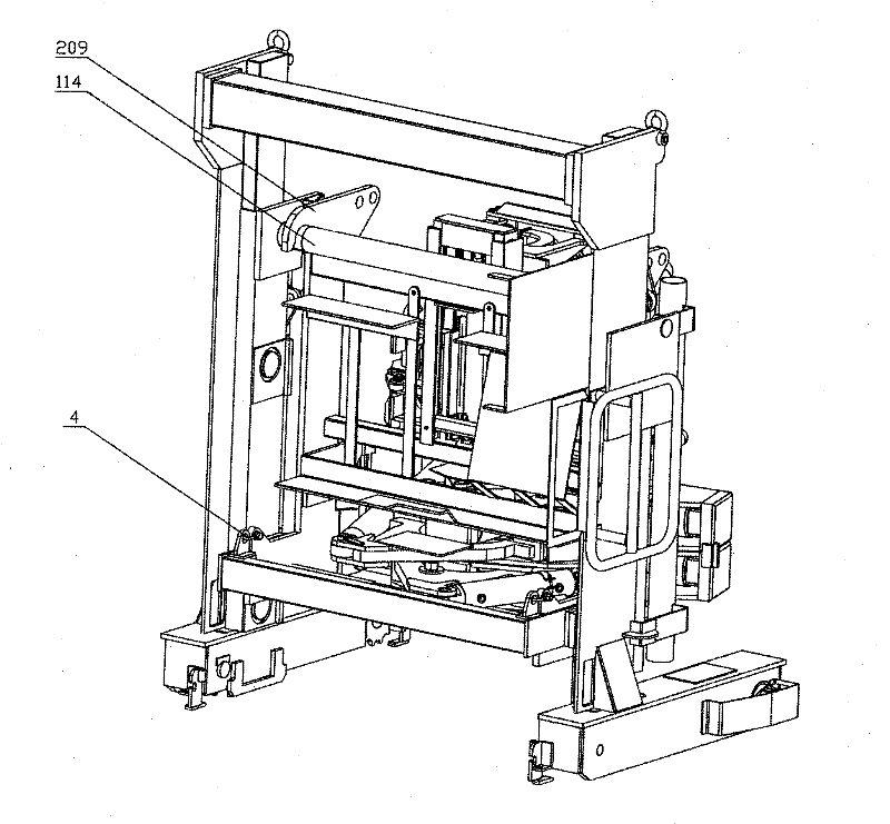
[0027] Example 2: Combining Figure 2-Figure 6 , the lifting vehicle (1) of the present invention moves on the guide rail (3), and the pincer head frame (2) is articulated on the slide rail column beam of the lifting vehicle (1) through the upper hook plate of the upper back frame splint (209) (114), and the lower beam (125) of the slide rail (125) is connected with the lower hole of the back frame splint (209) by a shackle (4).

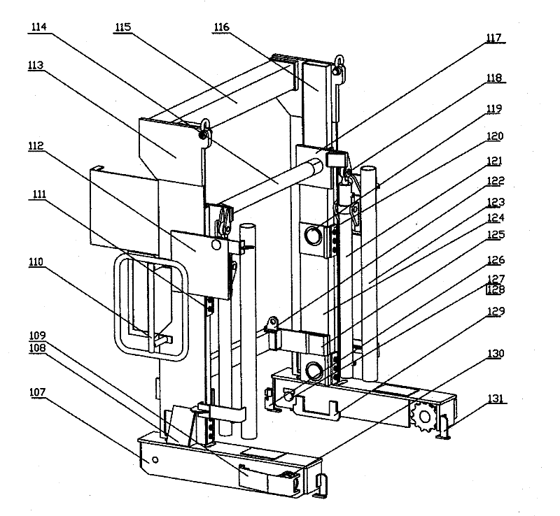
[0028] figure 2 Be lift car (1): lift car (1) is made up of left and right side frame and beam. The left and right side frames are installed on two guide rails (3) respectively, and the drive gear (102) at the bottom of the left and right side frames is engaged with the gear rack on the inside of the guide rail (3) to realize the advancement and retreat of the lift car (1). The transmission gear (102) is connected to the lift car hydraulic motor (130) transmission on the foot box outer plate (107) at the bottom of the left and right sides by bolts...


PUM


Abstract

The invention provides a floor rail type highly integrated intelligent iron roughneck, which integrates a lift car, a clamp head frame, a main back clamp and guide rails into a whole and consists of the lift car, the clamp head frame and the guide rails, wherein the lift car moves on the guide rails, the upper part of the clamp head frame is suspended and connected onto the lift car, in addition,the connection between the lift car and the lower part of the clamp head frame is realized through unscrewing, the lift car consists of a left side frame, a right side frame and a cross beam, the left side frame and the right side frame are respectively arranged on the two guide rails, the lift car drives a transmission gear to rotate through a lift car hydraulic motor for realizing the moving onthe guide rails. The floor rail type highly integrated intelligent iron roughneck can realize the application of a large-torque and wide-pipe-diameter-range rotary thread punching device and is applicable to the unscrewing on drill rods in any dimensions. The lift car, the clamp head frame, the main back clamp and the guide rails are integrated into a whole, so the weight of the whole equipment is greatly reduced, and the work efficiency is improved. The floor rail type highly integrated intelligent iron roughneck has the advantages that the automation degree is high, the full-process automatic operation of the work process can be realized, and the rotary thread punching operation of the whole site can be completed by one worker.

Description

(1) Technical field [0001] The invention relates to oil drilling engineering technology, in particular to a floor rail type highly integrated intelligent iron driller. (2) Background technology [0002] Iron driller is a multi-functional, safe and efficient drilling tool spinner, an important auxiliary equipment in automatic drilling, and has been widely used in foreign oil production. However, most of the iron drillers are arm-type structures. The iron drillers are installed on the lifting column through double-section or multi-section mechanical arms. The rotary punching device requires light weight and compact structure. Therefore this kind of structure can't realize the drilling pipe operation of big torque, big pipe diameter, and the working space is limited by the retractable range of mechanical arm. The spinner of the iron driller's pliers is generally connected with the punching device through a compression spring or a tension spring to realize a floating support co...

Claims


Application Information

Patent Timeline
Patent Type & Authority Applications(China)
IPC IPC(8): E21B19/16
Inventor 孙敬颋白勇刘春来闫志超魏荣佟万成
Owner 金华萨博思石油机械有限公司
Why Eureka
Try Eureka