Floater-guided steam trap

A pilot-operated, steam trap technology, applied in the direction of steam traps, mechanical equipment, etc., can solve problems such as uneven wear, air blockage, increased friction, etc., to achieve a wide range of applicable working conditions, sensitive and reliable action, and improve the use of performance effect

Active Publication Date: 2013-03-27
YINGQIAO MACHINERY MFG
View PDF7 Cites 0 Cited by
  • Summary
  • Abstract
  • Description
  • Claims
  • Application Information

AI Technical Summary

Problems solved by technology

[0003] The existing ball float pilot super large displacement steam traps generally have shortcomings such as large volume, heavy weight, and unreasonable structure. Usually, the float pilot valve of the valve is located on the upper part of the valve cavity, and its exhaust device is manually operated. When starting up the machine for the first time, you must manually open the exhaust valve first, and then the condensed water can enter the valve cavity smoothly after the non-condensable gas is removed. Otherwise, air blockage will occur and the valve will not operate normally.
In addition, the piston assembly and main valve parts of this kind of float pilot super large displacement steam trap are designed to be installed obliquely. Friction, easy to wear, short life, thus affecting the performance of the trap

Method used


Image

  • Floater-guided steam trap
  • Floater-guided steam trap
  • Floater-guided steam trap

Examples


Embodiment 1

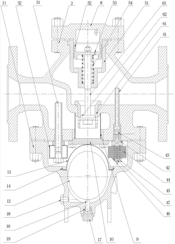
[0043] Embodiment 1 (float pilot type steam trap of bimetallic automatic air exhaust device)

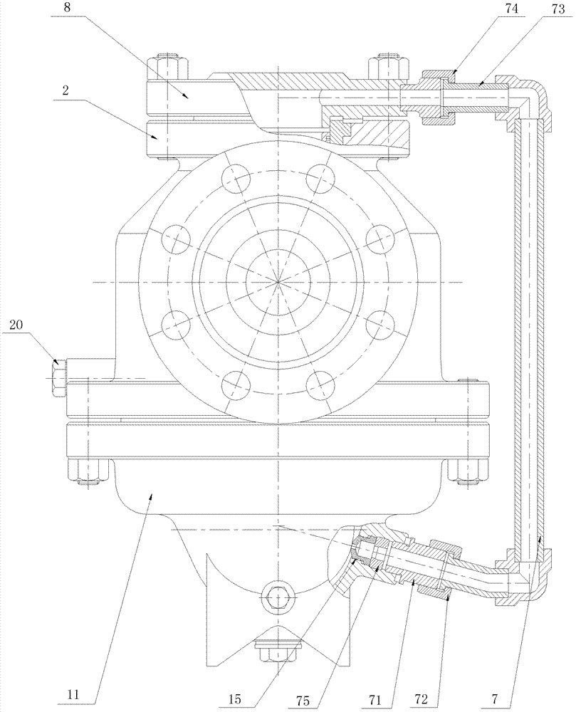
[0044] see figure 1 and 3 ~6, Embodiment 1 of the present invention is provided with a float pilot valve, an upper valve body 2, a filter device, an exhaust device, a piston assembly, a main valve, a conduit and a valve cover 8.

[0045] The floating ball pilot valve is provided with a lower valve body 11, a floating ball 12, a cover 13, a fixed circlip 14, a pilot valve seat 15, an adjusting bolt 16, a lower joint 71 and a blowdown bolt 18; the filtering device is provided with Inlet pipe 31 and filter screen 32; The piston assembly is provided with a piston body 51, a piston 52, three uniformly distributed pressure relief holes 53 and a spring 54; the main valve is provided with a main valve seat 61, a main valve core 62 And the main valve stem 63.

[0046] The upper valve body 2 and the lower valve body 11 are connected by stud bolts, and the upper valve body 2 and the lower va...

Embodiment 2

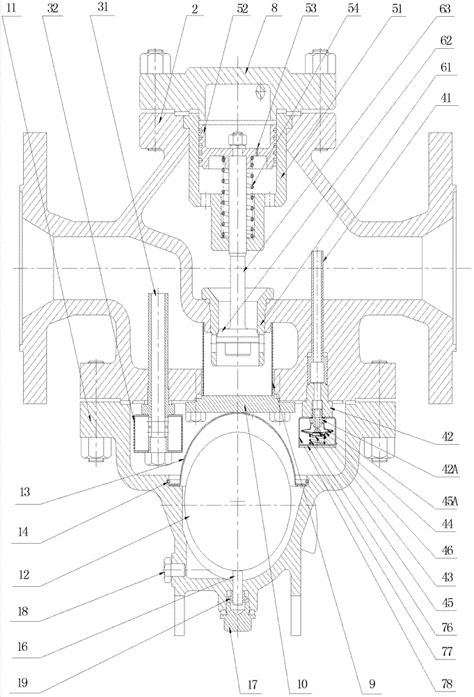
[0053] Embodiment 2 (float pilot type steam trap of the bellows automatic exhaust device)

[0054] see figure 2 and 7 , similar to Embodiment 1, the difference is that the exhaust device is provided with an exhaust pipe 41, a large exhaust valve seat 42, a small exhaust valve seat 42A, an exhaust valve core 43, a diaphragm 44, and a bellows upper cover 45, bellows lower cover 45A, limit plate 46, spring 76, pressure plate 77 and bellows cover 78, described exhaust pipe 41 is directly connected to the outlet cavity of upper valve body 2, exhaust pipe 41 is exhausted by large valve seat 42 Tighten, the exhaust small valve seat 42A and the large valve seat 42 are screwed and fixed, the upper cover 45 of the bellows box is welded together with the lower cover 45A of the bellows box and the diaphragm 44, the exhaust valve core 43 is connected with the diaphragm 44 and the limit plate 46 spot welding connection, the lower end hole of the bellows cover 78 is inserted into the thre...


PUM


Abstract

The invention discloses a floater-guided steam trap, which relates to a steam trap. The invention provides a floater-guided super large displacement steam trap, which is provided with an internal automatic exhaust device, has a rational structure, stable and reliable performance and long service life and is convenient to maintain. The floater-guided super large displacement steam trap comprises afloater-guided valve, an upper valve body, a filtering device, an exhaust device, a piston combined piece, a main valve, a guide pipe and a valve cap, wherein the floater-guided valve comprises a lower valve body, a floater, an isolating hood, a fixing clamp spring, a guide valve seat, a regulating bolt, a lower movable joint and a pollution discharging bolt; the filtering device comprises an inlet pipe and a filtering screen; the piston combined piece is provided with a piston body, a piston, a decompression hole and a spring; the main valve is provided with a main valve seat, a main valve core and a main valve rod; the upper valve body is connected with the lower valve body; the upper valve body and the lower valve body are divided into an upper valve cavity and a lower valve cavity by an internal cap; the filtering device and the exhaust device are arranged in the lower valve body; the piston combined piece is arranged in the upper valve body; and the valve cap covers the upper part of the upper valve body and is connected with the upper valve body.

Description

technical field [0001] The invention relates to a steam trap, in particular to a float pilot type super large displacement steam trap. Background technique [0002] The existing float pilot super large displacement steam trap is mainly composed of float pilot assembly, valve cover, valve body, filter device, exhaust device, piston, main valve core, main valve seat and other components. Its working principle: when the cold gas enters the float pilot valve cavity, the exhaust device needs to be manually opened to allow the condensed water to enter the valve cavity smoothly, and then close the exhaust device after the valve drains normally. When the condensed water enters the valve chamber, the floating ball rises with the water level and automatically opens the seat hole of the pilot valve, and the condensed water enters the piston chamber through the connecting pipe. Since the piston pressure area is larger than the main valve pressure area, the downwardly inclined piston is ...

Claims


Application Information

Patent Timeline
Patent Type & Authority Patents(China)
IPC IPC(8): F16T1/20F16T1/38
Inventor 洪新强洪新伟乔存德洪有福洪艳铌陈永明
Owner YINGQIAO MACHINERY MFG
Why Eureka
Try Eureka