
Film attachment method of light guide plate

A light guide plate and film material technology, which is applied in chemical instruments and methods, light guides, optics, etc., can solve problems affecting the manufacturing process, incomplete pasting, and pasting deviations, and achieve uniform distribution of the force-bearing area, simple film material numbers, and The effect of streamlining inventory management

Inactive Publication Date: 2011-12-21
DYNACOLOR
View PDF2 Cites 7 Cited by
  • Summary
  • Abstract
  • Description
  • Claims
  • Application Information

AI Technical Summary

Problems solved by technology

[0006] The above-mentioned process speed cannot be improved, and the bonding efficiency is not high, and because of the manual pasting method, there is often a gap between the film material and the film material attachment surface due to uneven force, resulting in incomplete pasting and sticking Deviations will easily lead to an increase in the defect rate in the overall process, which will lead to an increase in material costs and processing costs, and affect subsequent related processes

Method used


Image

  • Film attachment method of light guide plate
  • Film attachment method of light guide plate
  • Film attachment method of light guide plate

Examples


Embodiment Construction

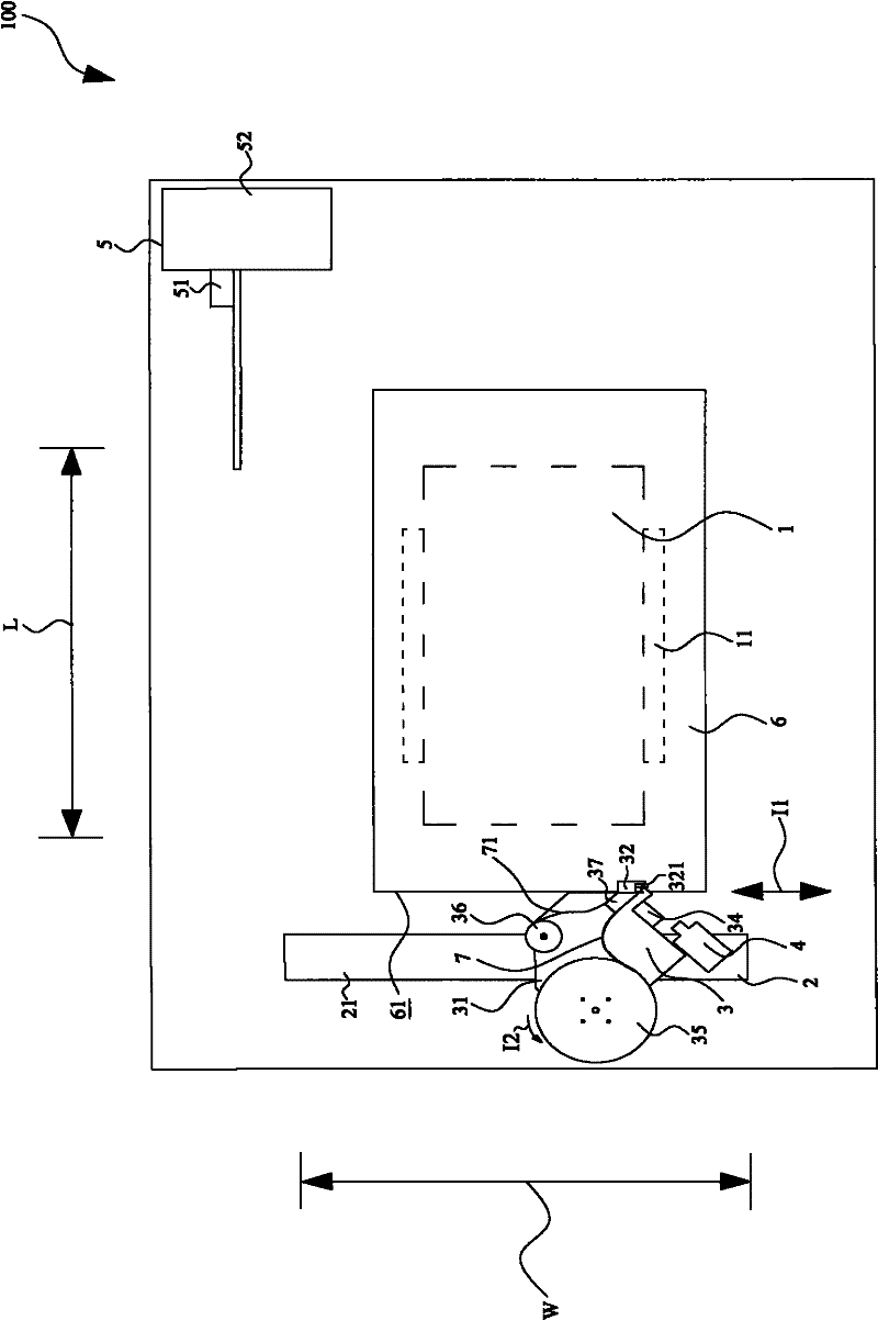
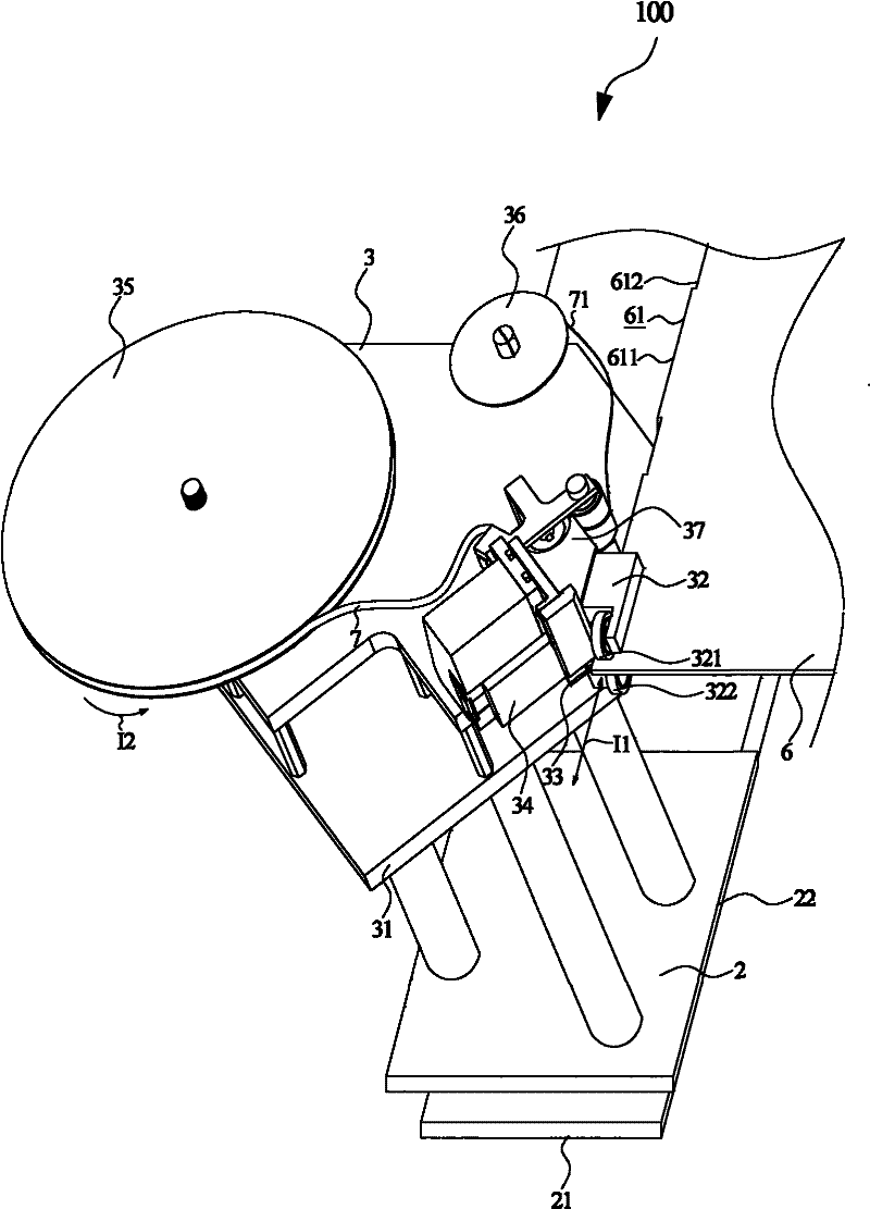
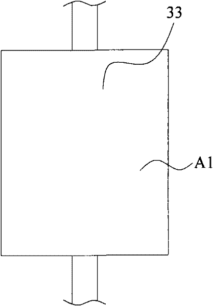
[0039] see also Figure 1 to Figure 4 shown, figure 1 It is the top view of the film material attaching device of the film material attaching method of the light guide plate according to the embodiment of the present invention, figure 2 It is a schematic diagram of the actual operation of the film material attaching mechanism of the film material attaching method of the light guide plate according to the embodiment of the present invention, 3A to 3D It is a schematic diagram of the narrow surface and the narrow line of the attachment member according to the embodiment of the present invention, Figure 4 It is a flow chart of an embodiment of a method for attaching a film material to a light guide plate of the present invention.

[0040] In the present invention, the film attaching device 100 for implementing the film attaching method includes a holding mechanism 1 , a sliding mechanism 2 , a film attaching mechanism 3 , a positioning sensing device 4 and an attaching devic...


PUM


Abstract

The invention discloses a method for attaching a film material of a light guide plate, comprising: placing the light guide plate on a supporting mechanism, moving the film material attaching mechanism to the film material attaching surface corresponding to one side of the light guide plate, and pressing the upper part of the moving member The pressing part and the lower pressing part press the light guide plate in the thickness direction of the light guide plate, the separation member separates the film material on the supply path of the film material from the profile, and the attachment member passes along the path of the light guide plate with a narrow surface or a The film that has been separated from the profile is moved and pressed flat on the film attachment surface of the light guide plate in the way of positive contact of the narrow line, and then the film that has not been separated from the profile is cut by the cutting member And it will not cut off the profile. Adopting the technical scheme of the invention can simplify the inventory management of membrane materials and solve various disadvantages caused by manual pasting.

Description

technical field [0001] The invention relates to the design of a method for attaching a film material, in particular to a method for attaching a film material to a light guide plate. Background technique [0002] In the technical field of backlight modules, the function of the light guide plate is to convert a point light source (light emitting diode LED) or a line light source (cold cathode tube CCFL) into a surface light source for use in a liquid crystal display panel. In the application of the light guide plate in the backlight module, in order to prevent the light from leaking from the side of the light guide plate, usually in the assembly production line, the light guide plate is first placed on the light guide plate holder by manual handling, and then manually. The light-shielding (or light-reflecting) film is attached to two or three sides (sides) of the light guide plate, so as to complete the action of the light guide plate to prevent light leakage. [0003] In the...

Claims


Application Information

Patent Timeline
IPC IPC(8): G02B6/00B32B37/10B32B38/04B32B38/18
Inventor 陈春生李政鸿林辰辅
Owner DYNACOLOR
Learn More