Gasification furnace chilling ring

A technology of gasification furnace and chilling ring, which is applied in the field of gasification furnace, can solve the problems of incomplete assembly, high price, burnt out downcomer, etc., and achieve the effect of simple assembly, simple processing and prolonging service life

Active Publication Date: 2017-05-10
DONGFANG BOILER GROUP OF DONGFANG ELECTRIC CORP
View PDF11 Cites 5 Cited by
  • Summary
  • Abstract
  • Description
  • Claims
  • Application Information

AI Technical Summary

Problems solved by technology

The material procurement cycle is long, the price is expensive, and it is not convenient for users to spare parts, and the maintenance time of the furnace is long
[0006]2. It is difficult to process the channel ring chamber formed by forging the outer large forging, and the accuracy is not easy to guarantee
[0007]3. Due to the internal structure, the outer ring pipe cannot be assembled as a whole, and the integrity cannot be realized during processing and assembly. It needs to be cut into several sections or assembled into upper and lower pieces for welding. Affect the assembly accuracy, and even cause local failure to form a water film, the protection of the downcomer will fail and the downcomer will be burned out, affecting the normal operation of the gasifier
If some openings are misaligned or not fully aligned during assembly, or the water flow distribution pressure of each small hole is inconsistent, a tight water curtain will not be formed in the downcomer, making it impossible to fully perform mass transfer and heat exchange.
[0009]5. The high-temperature syngas and slag directly scour the chilling ring, which will easily cause the outer ring pipe of the chilling ring to be scoured and perforated, cracked and deformed, and the spraying effect will be improved. If not, the water curtain cannot be formed, and the water film on the downcomer cannot be formed, and the chilling fails

Method used


Image

  • Gasification furnace chilling ring
  • Gasification furnace chilling ring
  • Gasification furnace chilling ring

Examples


Embodiment Construction

[0035] All features disclosed in this specification, or steps in all methods or processes disclosed, may be combined in any manner, except for mutually exclusive features and / or steps.

[0036] Any feature disclosed in this specification (including any appended claims, abstract and drawings), unless expressly stated otherwise, may be replaced by alternative features which are equivalent or serve a similar purpose. That is, unless expressly stated otherwise, each feature is one example only of a series of equivalent or similar features.

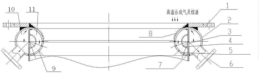
[0037] The structure and principle of the quenching ring of the gasifier of the present invention will be described in more detail below.

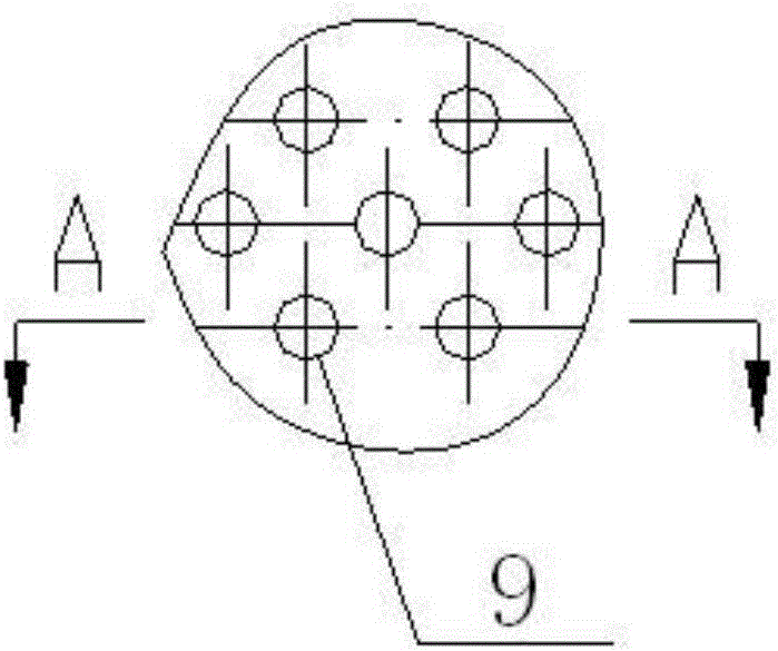
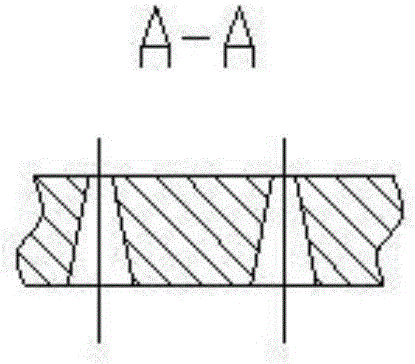
[0038] figure 1 A schematic diagram showing the structure of a quenching ring of a gasifier according to an exemplary embodiment of the present invention, Figure 2A Shows the arrangement of the spray holes on the distribution ring in the quenching ring of the gasifier according to an exemplary embodimen...


PUM

PropertyMeasurementUnit
diameteraaaaaaaaaa

Abstract

The invention discloses a gasification furnace chilling ring, comprising an annular fixing plate, a channel ring, a distance ring, an inner ring, a distribution ring and a plurality of chilling water inlet pipes, wherein the channel ring is fixed at the bottom of the annular fixing plate, the distribution ring is provided with a plurality of spraying holes arrayed in a staggered way; the distance ring is arranged in the middle of the channel ring and divides the channel ring into a channel chamber on the outer side and a distribution chamber on the inner side, the bottom of the distance ring is in butt joint with a downcomer of a gasification furnace, the height of the distance ring is adjustable, a chilling water channel is formed between the top of the distance ring and the inner wall of the top of the channel ring, and a plurality of fixed-distance steel balls for controlling an annular space between the distribution ring and the distance ring are arranged between the distribution ring and the distance ring; the inner ring has a semi-pipe structure and is fixed on the distance ring, the inner ring is located in the distribution chamber, and the inner ring is provided with a plurality of holes for liquid passing and ventilating; the plurality of chilling water inlet pipes are arranged on the lower outer side of the channel ring and are communicated with the channel chamber; the upper surface of the inner side of the channel ring is evenly provided with a plurality of slag nails, and a refractory material is applied among the slag nails.

Description

technical field [0001] The invention relates to the technical field of a gasification furnace, and more specifically relates to a quenching ring of a gasification furnace. Background technique [0002] The gasifier is the key equipment in the coal gasification plant. Although different schools of gasification technologies have different technological processes, the operating environment of the key equipment gasifier is relatively poor, and it is in a harsh environment of high temperature, high pressure and high corrosion. The pulverized coal or coal-water slurry is incompletely burned in the gasification chamber of the gasifier to generate high-temperature syngas and slag at about 1500°C, and then descends into the quenching chamber. The function of the quenching chamber is to cool down the high-temperature syngas and slag And realize gas slag separation. [0003] The boundary between the gasification chamber and the quenching chamber is the quenching ring. The functions of...

Claims


Application Information

Patent Timeline
Patent Type & Authority Applications(China)
IPC IPC(8): C10J3/84
CPCC10J3/845Y02E20/18
Inventor 应永茂王锦生周松锐
Owner DONGFANG BOILER GROUP OF DONGFANG ELECTRIC CORP
Why Eureka
Try Eureka