Method of flattening the substrate
A flattening and substrate technology, applied in the field of flattening process, can solve problems such as rough patterning and yield reduction, and achieve the effect of improving flatness
- Summary
- Abstract
- Description
- Claims
- Application Information
AI Technical Summary
Problems solved by technology
Method used
Image

Examples
Embodiment Construction
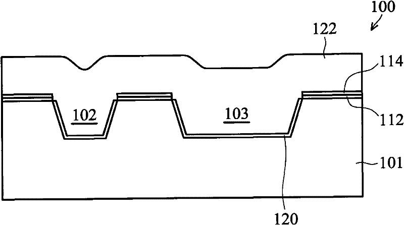
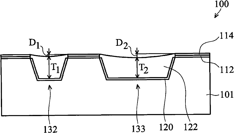
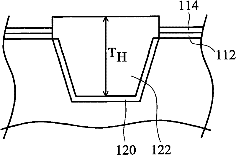
[0054] A number of different embodiments or examples are provided below to implement the features of the various embodiments of the invention. The following will briefly describe the structure and arrangement of specific embodiments. Of course, the following description is only an example, not intended to limit the present invention. In addition, in each example of the present invention, repeated component numbers may appear, but the above repetition is only used to briefly and clearly describe the present invention, and does not represent the relationship between the various implementation examples and structures.
[0055] Chemical mechanical polishing (CMP for short) is a process used to remove a film layer from a substrate surface, and it is usually used to remove a film that is undulating on the substrate surface. This process removes surface relief across the entire substrate due to the chemical mechanical polishing pad's pressure on the entire substrate surface. CMP can...
PUM
 Abstract
Description
Claims
Application Information
 - Generate Ideas
- Intellectual Property
- Life Sciences
- Materials
- Tech Scout
- Unparalleled Data Quality
- Higher Quality Content
- 60% Fewer Hallucinations
Browse by: Latest US Patents, China's latest patents, Technical Efficacy Thesaurus, Application Domain, Technology Topic, Popular Technical Reports.
© 2025 PatSnap. All rights reserved.Legal|Privacy policy|Modern Slavery Act Transparency Statement|Sitemap|About US| Contact US: help@patsnap.com