Handheld communication device with coupled slot antenna module
A slot antenna and communication device technology, applied in the field of handheld communication devices, can solve the problems of signal loss, signal transmission loss, high fixation technology, etc., and achieve the effects of improving radiation gain value, high return loss, and high radiation performance
- Summary
- Abstract
- Description
- Claims
- Application Information
AI Technical Summary
Problems solved by technology
Method used
Image

Examples
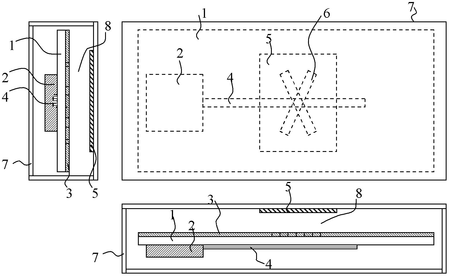
Embodiment 1
[0047] Depend on figure 1 It can be seen from the top view and the side view that the radio frequency module 2 is coupled on the surface of the dielectric substrate 1 for converting signals generated by various electronic components on the PCB into radio frequency signals. In this embodiment, the feeder 4 is coupled to the surface of the dielectric substrate 1 on the same side as the radio frequency module 2 , one end of which is connected to the radio frequency module 2 , and extends toward a long axis substantially parallel to the dielectric substrate 1 . The feeder 4 usually also includes a stub, and the feeder is used to feed signals to the radio frequency module 2 .
[0048] The above-mentioned ground plane 3 is coupled on the other surface of the dielectric substrate 1 where the above-mentioned radio frequency module 2 is located, its size is about the same as the above-mentioned substrate, and it is usually made of conductive material (such as a metal plate) for groundi...
Embodiment 2
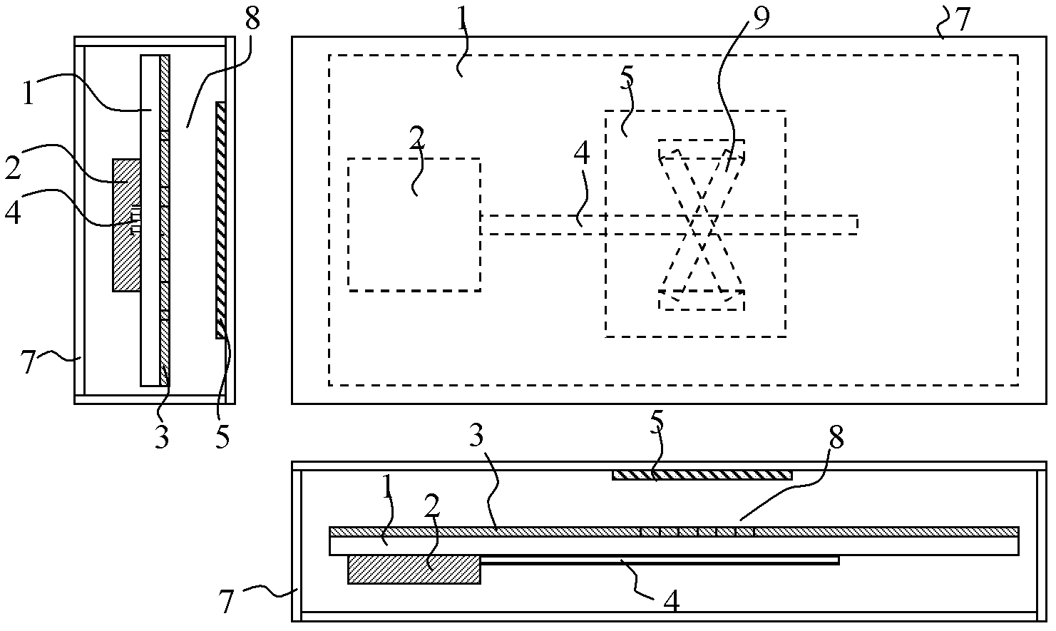
[0055] figure 2 Shown are three views of the slot antenna of the present invention. This embodiment is similar to the above embodiment, so the details of the same structure will not be described in detail. The antenna structure includes a dielectric substrate 1 , a ground plane 3 , a radiation plate 5 and an 8-shaped coupling slot 9 .
[0056] Depend on figure 2 It can be seen from the top view and side view that the present embodiment is characterized in that the 8-shaped coupling slot 9 is on the ground plane 3, by figure 2 It can be seen from the front view that the feeder 4 roughly passes through the intersection of the 8-shaped coupling slot 9 . The feeder 4 is usually a signal transmission line for transmitting communication signals. The radiation plate 5 is connected to the inner side of the dielectric housing 7 , and its area is about larger than that of the figure-eight coupling slot 9 , and is located at the position of the figure-eight coupling slot 9 . The ...
PUM
| Property | Measurement | Unit |
|---|---|---|
| Angle | aaaaa | aaaaa |
| Area | aaaaa | aaaaa |
| Volume | aaaaa | aaaaa |
Abstract
Description
Claims
Application Information
 - Generate Ideas
- Intellectual Property
- Life Sciences
- Materials
- Tech Scout
- Unparalleled Data Quality
- Higher Quality Content
- 60% Fewer Hallucinations
Browse by: Latest US Patents, China's latest patents, Technical Efficacy Thesaurus, Application Domain, Technology Topic, Popular Technical Reports.
© 2025 PatSnap. All rights reserved.Legal|Privacy policy|Modern Slavery Act Transparency Statement|Sitemap|About US| Contact US: help@patsnap.com