Fast chopper circuit and method for switched reluctance motor drive system

A technology of switched reluctance motor and drive system, applied in the direction of single motor speed/torque control, control system, control/regulation system, etc. Burnout of the switch tube and other problems, achieve the effect of fast action response, simple and reliable circuit structure, and reduce torque ripple

Inactive Publication Date: 2011-12-21
SOUTHEAST UNIV
View PDF7 Cites 18 Cited by
  • Summary
  • Abstract
  • Description
  • Claims
  • Application Information

AI Technical Summary

Problems solved by technology

This invention solves the problem that the switching tube of the power converter may be burned due to the large delay in the on and off

Method used


Image

  • Fast chopper circuit and method for switched reluctance motor drive system
  • Fast chopper circuit and method for switched reluctance motor drive system
  • Fast chopper circuit and method for switched reluctance motor drive system

Examples


Embodiment Construction

[0029] The present invention will be described below with reference to the accompanying drawings.

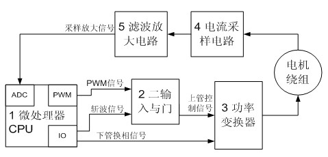
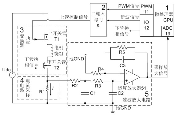
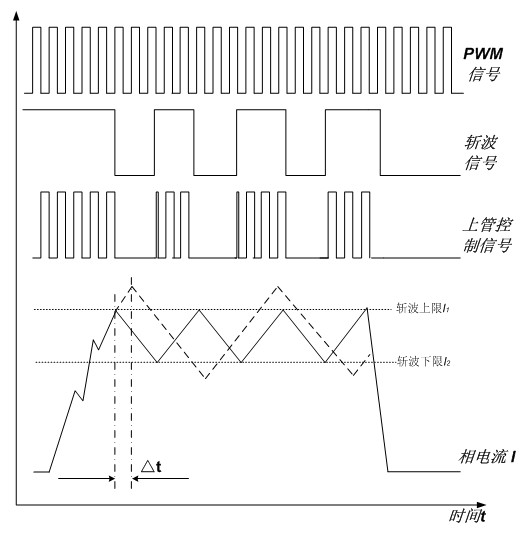
[0030]The invention discloses a fast chopper circuit and method for a switched reluctance motor drive system, which can quickly switch off The control signal of the upper switching tube of the power converter is cut off, so as to achieve a fast chopping effect, and the PWM module of the microprocessor CPU does not need to be turned off. The method and the circuit solve the problem that the switching tube of the power converter may be burnt due to the large delay in the on and off of the output signal of the PWM module of the microprocessor CPU, which leads to the untimely response of the software chopping action. The method and circuit structure are simple, reliable and easy to implement.

[0031] Taking one phase of the power converter and its related control circuit in the three-phase switched reluctance motor as an example, the arrow shows the flow direction of the signal. ...


PUM


Abstract

In the fast chopper circuit and method of the switched reluctance motor drive system, the current sampling circuit (4) collects the instantaneous value of the phase winding current of the motor, and transmits it to the microprocessor (1) in real time, and the microprocessor (1) judges the motor Whether the instantaneous value of the phase winding current needs chopping, and output the pulse width modulation signal and the chopping signal according to the judgment result. Control signal to control its upper switch tube. After the microprocessor (1) makes an internal judgment, it outputs the pulse width modulation signal and the chopping signal to the two-input AND gate (2) through the pulse width modulation module (11) and the input and output module (12): if the current is higher than the chopping signal If the current is lower than the lower limit of chopping, the chopping signal is set high to turn on the upper tube of the power converter (3). Control signal; realize fast chopping control of the power converter.

Description

technical field [0001] The invention relates to a fast chopper circuit and method of a switched reluctance motor drive system, which can quickly shut down when the switched reluctance motor controller works in the combined control mode of pulse width modulation (PWM) and current chopping (CCC). The upper switching tube of the power converter controls the signal, so as to achieve a fast chopping effect, and does not need to turn off the PWM module of the microprocessor CPU. The invention solves the problem that the switch tube of the power converter may be burned due to the large delay in the on and off of the output signal of the PWM module of the microprocessor CPU, which leads to the untimely response of the software chopping action. It belongs to the field of motor control. Background technique [0002] Switched reluctance motor is a new type of speed regulation motor, which has the advantages of both DC and AC speed regulation systems. It is the latest generation of ste...

Claims


Application Information

Patent Timeline
IPC IPC(8): H02P6/08H02M3/135H02P25/092
Inventor 钟锐秦明亮陈磊刁龙孙伟锋陆生礼时龙兴
Owner SOUTHEAST UNIV
Why Eureka
Try Eureka