Motor Position Detection Circuit Using Isolated Resolver

A resolver and motor position technology, applied in the direction of electronic commutator, etc., can solve the problems of poor load adaptability, poor system stability, limited amplification ability, etc., and achieve the effects of improved stability, low cost, and wide application range

Active Publication Date: 2011-12-21
UNITED AUTOMOTIVE ELECTRONICS SYST
View PDF4 Cites 12 Cited by
  • Summary
  • Abstract
  • Description
  • Claims
  • Application Information

AI Technical Summary

Problems solved by technology

[0004] The use of operational amplifiers has the disadvantage of limited amplification capability, while direct use of p

Method used


Image

  • Motor Position Detection Circuit Using Isolated Resolver
  • Motor Position Detection Circuit Using Isolated Resolver
  • Motor Position Detection Circuit Using Isolated Resolver

Examples


Example Embodiment

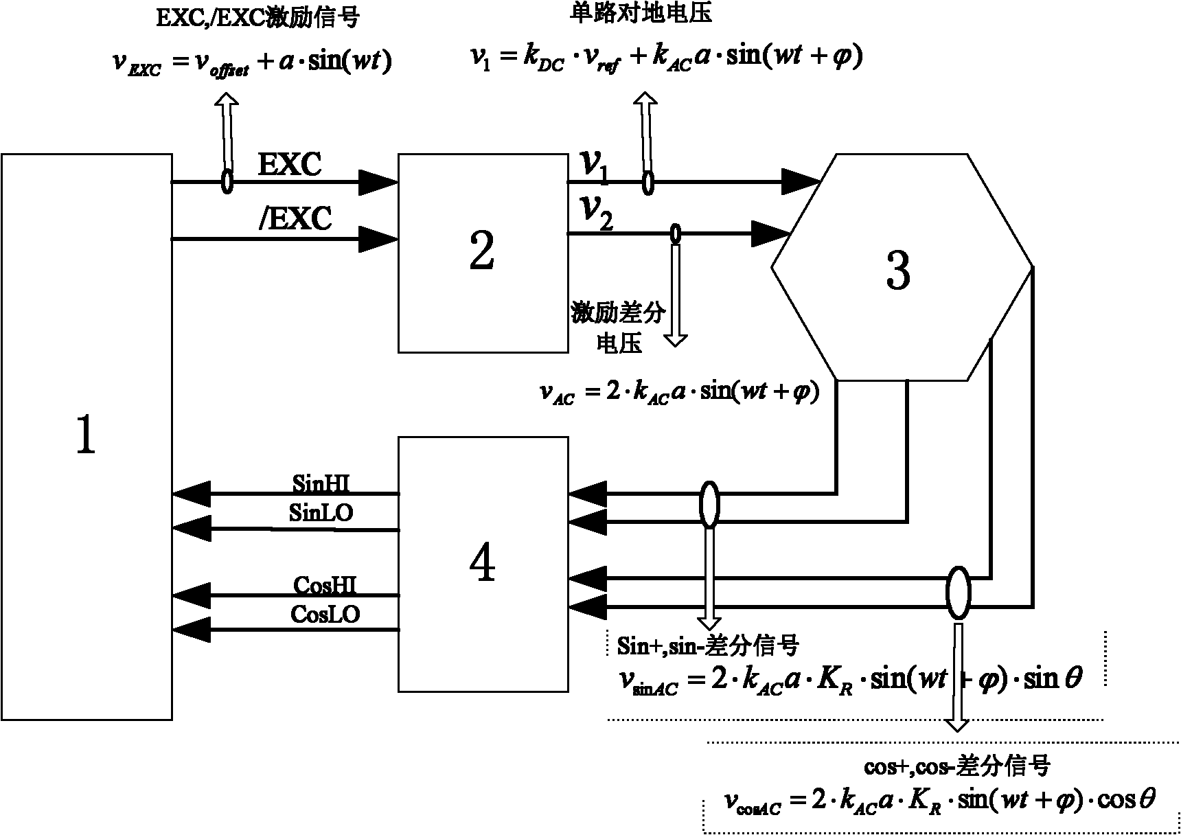
[0021] The motor position detection circuit of the present invention adopts an isolated resolver, such as figure 1 As shown, it includes a decoding chip 1, a Buffer circuit 2, and a differential signal conditioning circuit 4. The output of the decoding chip 1 is connected to the input of the Buffer circuit 2, and the output of the Buffer circuit 2 is connected to the input of the resolver 3. The resolver 3 outputs a sine and cosine differential signal to the differential signal conditioning circuit 4, and the differential signal conditioning circuit 4 processes the output signal to the input terminal of the decoding chip 1.

[0022] in figure 1 In, the single-channel ground signal of the excitation signal of decoding chip 1 can be expressed by formula (1),

[0023] v EXC =v offset +a·sin(wt) (1)

[0024] In the formula, a is the amplitude of the excitation signal EXC output by the decoding chip, v offset Is the DC component of EXC, and a·sin(wt) is the AC component of EXC.

[0025]...


PUM


Abstract

The invention discloses a motor position detecting circuit utilizing an isolating type rotating transformer, and the motor position detection comprises a decoding chip, a Buffer circuit and a differential signal regulating circuit, wherein the output end of the decoding chip is connected with the input end of the Buffer circuit; the output end of the Buffer circuit is connected with the input end of the rotating transformer; the rotating transformer outputs a sine-cosine differential signal to the differential signal regulating circuit; the sine-cosine differential signal processed by the differential signal regulating circuit is input to the decoding chip; and the Buffer circuit comprises a front end filtering circuit, an operating and amplifying control circuit, a push-pull circuit and a drive protecting circuit. The power amplification of an excitation signal is realized by adopting the Buffer circuit which is powered by a power supply and has protection, thus the isolating type rotating transformer-adopted motor position detecting circuit can adapt to the drive capability of different loads, can realize a large-range change of differential voltage peaks and has the advantages of enhanced circuit stability, strong load adaptability and good interference resistance; and the differential signal regulating circuit with direct current bias can realize level matching between different rotating transformers and different decoding chips, so that the isolating type rotating transformer-adopted motor position detecting circuit has the advantages of simple circuit structure, low cost and wide application range.

Description

technical field [0001] The invention relates to a rotor position detection circuit of a high-power drive motor for a new energy vehicle, in particular to a motor position detection circuit using an isolated rotary transformer. Background technique [0002] In the rotor position detection circuit of the motor, photoelectric encoders and resolvers are commonly used at present. The photoelectric encoder is a sensor that converts the mechanical angular displacement on the output shaft into pulses or digital quantities through photoelectric conversion. A transformer is an electromagnetic sensor used to measure the angular displacement and angular velocity of a rotating object. Compared with photoelectric encoders, resolvers have the advantages of high reliability, high stability, low cost, and insensitivity to environmental factors such as mechanical vibration, temperature, and humidity. A mainstream sensor. [0003] At present, the mainstream structure of the resolver is isola...

Claims


Application Information

Patent Timeline
IPC IPC(8): H02P6/16
Inventor 张林刘皞星
Owner UNITED AUTOMOTIVE ELECTRONICS SYST
Why Eureka
Try Eureka