Eureka AIR delivers breakthrough ideas for toughest innovation challenges, trusted by R&D personnel around the world.

A loop response time measuring device and method for an atomic frequency standard

A loop response, atomic frequency standard technology, applied in the direction of automatic power control, electrical components, etc., can solve the problems of complex loop analysis, difficult loop response time analysis, inability to collect quantum frequency discrimination signals, etc., to achieve improved accuracy. Effect

Inactive Publication Date: 2011-12-21
JIANGHAN UNIVERSITY
View PDF3 Cites 23 Cited by
  • Summary
  • Abstract
  • Description
  • Claims
  • Application Information

AI Technical Summary

Problems solved by technology

[0004] In the servo control loop of the passive atomic frequency standard, the quantum system, VCXO and the phase-sensitive detector in the servo loop all have nonlinear characteristics, the loop analysis is very complicated, and the loop response time of the whole system is even more difficult to analyze
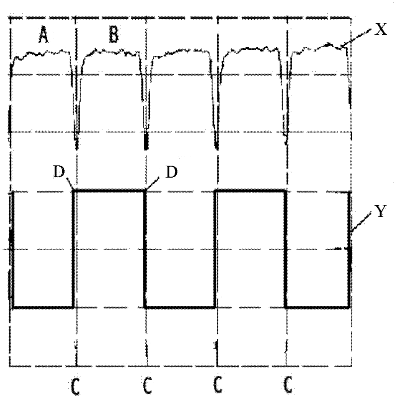
Among them, the actual relaxation time of the quantum system limits the loop response time of the entire system to a large extent. In addition, the phase problem of each circuit module brings great difficulties to the acquisition of the error signal of the servo loop and the output of the corresponding correction voltage. major inconvenience, such as figure 2 As shown, due to the relaxation time of the quantum system and the phase difference of the circuit, the servo loop cannot actually collect the voltage difference between the quantum discrimination signal X at point A and point B according to the corresponding synchronous reference signal Y

Method used


Image

  • A loop response time measuring device and method for an atomic frequency standard
  • A loop response time measuring device and method for an atomic frequency standard
  • A loop response time measuring device and method for an atomic frequency standard

Examples


Embodiment 1

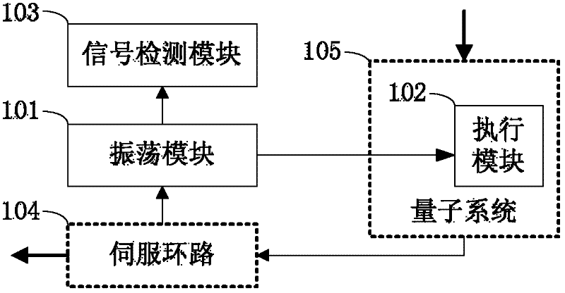
[0034] An embodiment of the present invention provides a loop response time measurement device, such as image 3 As shown, the device includes an oscillation module 101 , an execution module 102 and a signal detection module 103 . Wherein, the input end of the oscillation module 101 is connected with the servo loop 104 of the atomic frequency standard, and is used to receive the output signal of the servo loop 104 of the atomic frequency standard, and the output signal of the servo loop 104 of the atomic frequency standard Output after inversion; the execution module 102 is connected to the output terminal of the oscillation module 101, and is used to act according to the output signal of the oscillation module 101, so as to control whether the quantum system 105 of the atomic frequency standard can complete quantum frequency discrimination The signal detection module 103 is connected to the output terminal of the oscillation module 101, and is used to measure the oscillation ...

Embodiment 2

[0037] An embodiment of the present invention provides a loop response time measurement device for an atomic frequency standard, such as Figure 4 As shown, in this embodiment, the atomic frequency standard includes a voltage-controlled crystal local oscillator 204, an electronic circuit 205, a programmable logic chip 206, a quantum system 207 and a servo loop 208, and the quantum system 207 includes at least a spectral lamp 2071, integrated filter resonance bubble 2072, magnetic shield 2073, constant temperature 2074 and cavity 2075, the aforementioned components complete the work of a standard atomic frequency standard, and its working principle is the same as that of a traditional atomic frequency standard, which is well known to those skilled in the art, so A detailed description is omitted here. It should be noted that, in this embodiment, the programmable logic chip 206 is a part of the servo loop 208 , which is represented independently for the convenience of descriptio...

Embodiment 3

[0052] The embodiment of the present invention provides a method for measuring the loop response time by using the device in Embodiment 1, such as Figure 7 As shown, the method specifically includes the following steps:

[0053] Step 301: Obtain the oscillation period of the oscillation module;

[0054] Step 302: measuring the oscillation period of the oscillation loop;

[0055] Step 303: Calculate the loop response time of the atomic frequency standard according to the oscillation period of the oscillation loop and the oscillation period of the oscillation module. Specifically, the loop response time of the atomic frequency standard is equal to half of the difference between the oscillation period of the oscillation loop and the oscillation period of the oscillation module.

[0056] The method for measuring the loop response time of the atomic frequency standard in this embodiment, by forming an oscillation loop with the oscillation module, the execution module, and the at...


PUM


Abstract

The invention discloses a loop response time measuring device and method used for an atomic frequency standard. The device comprises an oscillation module, an executing module and a signal detecting module, wherein the oscillation module is used for receiving an output signal of a servo loop of an atomic frequency standard and outputting the signal after reversing the phase of the output signal of the servo loop of the atomic frequency standard; the executing module is used for acting according to the output signal of the oscillation module to control the quantum system of the atomic frequency standard to finish the quantum frequency discrimination; and the signal detecting module is used for measuring the oscillation period of the oscillation loop according to the output signal of the oscillation module, and the oscillation loop consists of an oscillation module, an executing module and an atomic frequency standard. The method comprises the following steps of: obtaining the oscillation period of the oscillation module; measuring the oscillation period of the oscillation loop; and calculating the loop response time of the atomic frequency standard according to the oscillation period of the oscillation loop and the oscillation period of the oscillation module. By adopting the device and the method provided by the invention, the loop response time of the atomic frequency standard system can be measured accurately.

Description

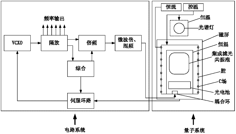
technical field [0001] The invention relates to the field of atomic frequency standards, in particular to a loop response time measurement device and method for atomic frequency standards. Background technique [0002] At present, passive atomic frequency standards are widely used in communication and other fields as highly stable and high-precision time synchronization sources. see figure 1 , the servo control loop of the passive atomic frequency standard is generally composed of a quantum system (also known as a physical system) and a circuit system. Among them, the quantum system provides an atomic resonance absorption line with stable peak frequency and narrow line width as a frequency reference, which acts as a quantum frequency discriminator; The output frequency is locked on the peak point of the atomic resonance absorption line. The basic working principle of the passive atomic frequency standard is that the output signal of the VCXO is frequency-multiplied and sy...

Claims


Application Information

Patent Timeline
IPC IPC(8): H03L7/26
Inventor 雷海东张霞詹志明
Owner JIANGHAN UNIVERSITY
Why Eureka
Eureka Blog
Learn More