Arrangement Structure of Submerged Nozzle for Shaped Billet Crystallizer

A technology for arranging structures and special-shaped billets, which is used in casting melt containers, manufacturing tools, metal processing equipment, etc. Nozzle service life and other issues, to achieve the effect of promoting reasonable solidification and continuous casting process, improving temperature and composition uniformity, reducing cracks and segregation

Inactive Publication Date: 2011-12-28
WISDRI ENG & RES INC LTD
View PDF3 Cites 13 Cited by
  • Summary
  • Abstract
  • Description
  • Claims
  • Application Information

AI Technical Summary

Problems solved by technology

However, the impact depth of the straight-through nozzle is relatively large, and the thermal center of the molten steel moves downward, which is not conducive to the effective floating of inclusions and the growth of the primary shell. Moreover, the molten steel flowing out of the straight-through nozzle is mainly concentrated in the triangular area, making The temperature and composition of the entire profiled billet vary greatly in the transverse direction, which easily leads to quality defects such as cracks and segregation
The third method is to use a single submerged nozzle to pour in the triangular area on one side of the profiled billet section, which will make the flow field and temperature field of the molten steel in the mold extremely unreasonable, resulting in various surface and internal quality of the billet. Problems occur frequently, and in serious cases, steel leakage accidents may occ

Method used


Image

  • Arrangement Structure of Submerged Nozzle for Shaped Billet Crystallizer
  • Arrangement Structure of Submerged Nozzle for Shaped Billet Crystallizer
  • Arrangement Structure of Submerged Nozzle for Shaped Billet Crystallizer

Examples


Example Embodiment

[0025] The following is combined with the examples and attachments Figure 1-4 The present invention is further explained, but the present invention is not limited.
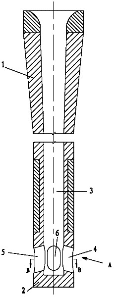
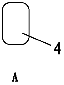
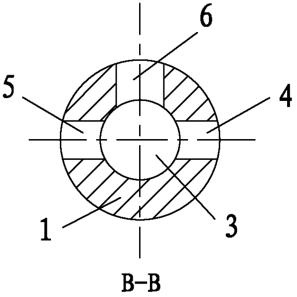
[0026] Such as Figure 1 ~ Figure 4 As shown, an immersed nozzle for a shaped blank crystallizer includes a nozzle side wall 1, and the lower end of the nozzle side wall 1 is a closed bottom 2. The bottom 2 can be convex, flat or concave. The central channel of the side wall 1 of the nozzle is an inner cavity 3, and the shape of the inner cavity can be round, square or chamfered square. Located above the bottom 2 of the side wall 1 of the nozzle, there are two symmetrical first and second water holes 4, 5 and a third water hole 6. These three water holes are all connected to the inner cavity of the nozzle, and the upper and lower edges are in the horizontal direction. The included angle is -25°~15°. The first and second water holes 4 and 5 are equal in size, and the shape is a chamfered square with a chamfering ra...


PUM


Abstract

The invention relates to an arrangement structure of submerged nozzles for a special-shaped billet crystallizer. In the special-shaped billet crystallizer, two submerged nozzles are respectively arranged in two triangular areas where the flange of the special-shaped billet and the web intersect and casting is performed simultaneously; the two nozzles The position is axially symmetrical along the vertical line of the web center of the profiled billet; the third holes of each nozzle are opposite and aligned with the center of the web, and the center line between the left and right sides of the third hole coincides with the center line of the web. The holes are distributed axially symmetrically along the centerline of the web. During pouring, the two nozzles are symmetrically arranged in the triangular area of ​​the profiled billet, the holes on the symmetrical sides of the nozzle are aligned with the two ends of the flange, and the third hole is aligned with the center of the web. The submerged nozzle and its arrangement can obviously disperse the impact force of molten steel, improve the thermal center of molten steel, promote the uniformity of temperature and composition in the cross-section of the crystallizer, facilitate the removal of inclusions and reduce cracks and segregation. Quality defects.

Description

technical field [0001] The invention belongs to the submerged nozzle device of the billet continuous casting crystallizer, and mainly relates to the arrangement structure of the submerged nozzle device for the mold of the special-shaped billet on the special-shaped billet. Background technique [0002] Continuous steel casting is the process of continuously cooling molten steel after smelting into a solid billet with a certain shape through a water-cooled copper crystallizer. During this process, the submerged nozzle device made of refractory material is usually used to continuously transport the molten steel in the upper station (tundish) into the crystallizer. The submerged nozzle can isolate the molten steel from the air, prevent the secondary oxidation of the molten steel, and ensure the purity of the molten steel; at the same time, by designing a suitable submerged nozzle structure size, a reasonable, stable and uniform mold flow field can also be obtained , to ensure ...

Claims


Application Information

Patent Timeline
IPC IPC(8): B22D11/10B22D41/50
Inventor 徐海伦马春武邵远敬叶理德
Owner WISDRI ENG & RES INC LTD
Why Eureka
Try Eureka