hydrogen burner

A burner, hydrogen technology, applied in the direction of burner, gas fuel burner, combustion method, etc., can solve the problems of high flue gas outlet temperature, low ignition energy, burning of furnace heating surface, etc., to ensure safe and stable operation , the effect of preventing tempering

Active Publication Date: 2011-12-28
ZHEJIANG TUFF BOILER
View PDF6 Cites 7 Cited by
  • Summary
  • Abstract
  • Description
  • Claims
  • Application Information

AI Technical Summary

Problems solved by technology

[0002] The ignition point of hydrogen is high, but its ignition energy is very small, so it is easy to catch fire and the flame spreads quickly. At the same time, the density of hydrogen is very small. It is difficult to ensure that hydrogen and oxygen in the air are fully mixed with a burner of general structure. Carried by the air flow, it quickly flows to the furnace outlet before complete combustion. The flame of hydrogen combustion is very long, which causes hydrogen to burn in the middle and rear of the furnace, resulting in excessive temperature of the flue gas outlet, which is easy to burn the heating surface of the boiler tail
[0003] At present, there are few hydrogen burners in industrial applications. Due to the low density of hydrogen, when hydrogen enters the furnace for combustion, the hydrogen is carried by the jet and quickly flows to the furnace outlet without complete combustion. Therefore, the flame of hydrogen combustion is very small. In severe cases, it may cause burning of the heating surface at the rear of the furnace

Method used


Image

  • hydrogen burner
  • hydrogen burner
  • hydrogen burner

Examples


Embodiment Construction

[0018] The specific implementation manners of the present invention will be further described in detail below in conjunction with the accompanying drawings.

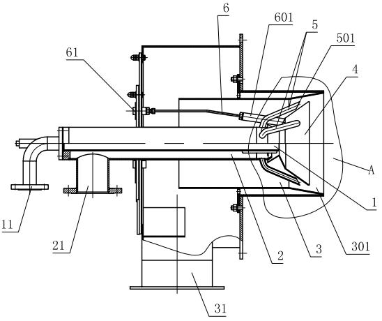
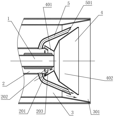
[0019] Such as Figure 1~4 As shown, the hydrogen burner includes a central channel 1 located at the axis, a middle channel 2 placed outside the central channel 1, and an outer ring channel 3 placed outside the middle channel. The central channel 1 is a nitrogen or air purge channel, and the central channel The rear part of 1 is provided with a nitrogen or air inlet 11, which is used to fill the furnace with nitrogen or air through this channel to replace the residual combustible gas trapped in the furnace when the furnace is shut down for a long time; the middle channel 2 is a hydrogen channel , one side of the middle channel 2 is provided with a hydrogen inlet 21; the outer ring channel 3 is an air channel, and the front end of the outer ring channel 3 is provided with a flared flame tube 301, and the flared structure ...


PUM


Abstract

The invention relates to a hydrogen gas combustor, which comprises a central channel, an intermediate channel and an outer ring channel. The hydrogen gas combustor is characterized in that a flame stabilizing disk is arranged at the front part of the outer ring channel; the flame stabilizing disk comprises a closing section and a flaring section; a plurality of ventilation holes are formed at thesmall end part of the flaring section; a plurality of vortex guiding cutting grooves are arranged at the large end part of the flaring section; the central channel and the front end of the intermediate channel are arranged in the flame stabilizing disk and are communicated with the flame stabilizing disk; the front part of the central channel is connected with a plurality of spray pipes; spouts of the spray pipes are attached to the outer wall of the flaring section on the flame stabilizing section; and an ignition device is arranged in the outer ring channel. According to the hydrogen gas combustor disclosed by the invention, by using a flame stabilizing disk structure, small part of hydrogen gas and air transmitting through the ventilation ports of the flame stabilizing disk and the vortex guiding cutting grooves are fully mixed inside the flame stabilizing disk; the most of hydrogen gas is sprayed out through the spray pipe and is paved and dispersed in the flame stabilizing disk; a fluid field structure is reasonably organized; the mixing of air and hydrogen gas is reasonably controlled; the hydrogen gas can be ensured to be completely combusted; the flame length is controlledwithin a reasonable range; and safe and stable operation of the boiler is ensured.

Description

technical field [0001] The present invention relates to a burner, in particular to a hydrogen burner for burning hydrogen. Background technique [0002] The ignition point of hydrogen is high, but its ignition energy is very small, so it is easy to catch fire and the flame spreads quickly. At the same time, the density of hydrogen is very small. It is difficult to ensure that hydrogen and oxygen in the air are fully mixed with a burner of general structure. Carried by the airflow, it quickly flows to the furnace outlet before complete combustion. The flame of hydrogen combustion is very long, which causes hydrogen to burn in the middle and rear of the furnace, resulting in excessively high flue gas outlet temperature, which is easy to burn the heating surface at the rear of the boiler. [0003] At present, there are few hydrogen burners in industrial applications. Due to the low density of hydrogen, when hydrogen enters the furnace for combustion, the hydrogen is carried by ...

Claims


Application Information

Patent Timeline
Patent Type & Authority Applications(China)
IPC IPC(8): F23D14/02F23D14/62F23D14/72
Inventor 邵福南徐鹤殷鸿斌
Owner ZHEJIANG TUFF BOILER
Why Eureka
Try Eureka