Thermal recovery system with improved thermal efficiency and thermoelectric combined production system equipped with the thermal recovery system

A heat recovery rate, heat recovery technology, applied in the direction of combined combustion mitigation, lighting and heating equipment, components of steam boilers, etc., can solve problems such as reduced combustion efficiency, deformation or cracking, and reduced durability

Active Publication Date: 2012-02-08
创意能源控股有限公司
View PDF6 Cites 5 Cited by
  • Summary
  • Abstract
  • Description
  • Claims
  • Application Information

AI Technical Summary

Problems solved by technology

Correspondingly, the exterior of a solid fuel burns well, but its interior may have limited access to the air required for combustion and may therefore not burn completely
This reduces the combustion efficiency
In addition, the inner wall of the combustion chamber is exposed to high-temperature gas for a long time, and it will be deformed or cracked after long-term use, thereby reducing durability

Method used


Image

  • Thermal recovery system with improved thermal efficiency and thermoelectric combined production system equipped with the thermal recovery system
  • Thermal recovery system with improved thermal efficiency and thermoelectric combined production system equipped with the thermal recovery system
  • Thermal recovery system with improved thermal efficiency and thermoelectric combined production system equipped with the thermal recovery system

Examples


Embodiment Construction

[0037] With reference to the accompanying drawings ( Figure 2 to Figure 8 ) to describe the heat recovery system with improved heat recovery rate according to the first embodiment of the present invention.

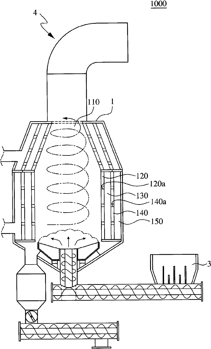
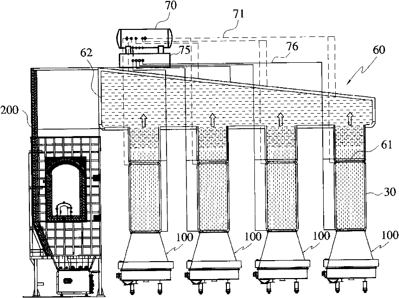
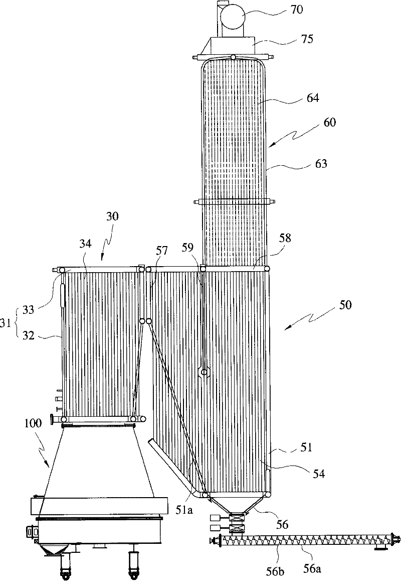
[0038] figure 2 A schematic diagram showing a heat recovery system with improved heat recovery rate according to a first embodiment of the present invention. image 3 yes figure 2 side view. Figure 4 show image 3 Schematic plan view of the gas discharge unit with U-shaped flow gas chamber. Figure 5 A sectional view of a combustion device according to the invention is shown. Image 6 show Figure 5 A cross-sectional view of one side of the combustion equipment. Figure 7 A sectional view of a feed unit of a combustion plant according to the invention is shown. Figure 8 is a longitudinal sectional view of the boiler in the heat recovery system according to the present invention.

[0039] According to the first embodiment of the present invention, a heat recov...


PUM


Abstract

The invention provides a thermal recovery system with improved thermal efficiency and a thermoelectric combined production system equipped with the thermal recovery system. A combustion apparatus includes a cylindrical combustion chamber surrounded by an inner wall. A cooling chamber comprises an intermediate wall spaced from the inner wall. Cooling water flows in and out lower and upper sides of the intermediate wall, to cool the inner wall by the cooling water that flows into a space formed between the inner and intermediate walls of the cooling chamber. A lateral combustion air supply chamber comprises an outer wall spaced from an outer side of the intermediate wall. Combustion air is supplied at an upper side of the outer wall to thereby make the air in a tangential direction with respect to the cylindrical outer wall turn and fall in a space formed between the intermediate wall and the outer wall, so that the combustion air is supplied to the combustion chamber via an opened lower portion of the lateral combustion air supply chamber.

Description

technical field [0001] The present invention relates to a heat recovery system with improved heat recovery rate, and more particularly to a heat recovery system which collects heat from gas and uses the collected heat as recovery energy, wherein the gas is Generated by burning solid fuel, etc. in a combustion chamber; and relates to a combined heat and power system using the heat recovery system. Background technique [0002] In general, industrial facilities that require industrial hot water, high-temperature steam or gas, respectively, generate thermal energy using a combustion device that ignites and burns fuel in a combustion vessel. In addition, from the viewpoints of economic efficiency and resource regeneration, solid fuels are widely used as fuels used in combustion devices, for example, Refuse Derived Fuel (RDF) that converts waste into fuel or waste plastic Refuse Plastic Fuel (RPF) that turns waste into fuel. [0003] However, since these existing combustion dev...

Claims


Application Information

Patent Timeline
Patent Type & Authority Applications(China)
IPC IPC(8): F22B31/04F22B33/18F22B37/00F01D15/10
CPCY02E20/12
Inventor 金相权
Owner 创意能源控股有限公司
Why Eureka
Try Eureka