
Combustion device with safety

A combustion device and safety technology, applied in the direction of burners, combustion methods, combustion types, etc., can solve the problems of incomplete combustion of oil lamps, unsmooth air circulation, and difficult heat loss, etc.

Active Publication Date: 2014-06-18
PRO IRODA INDS
View PDF7 Cites 6 Cited by
  • Summary
  • Abstract
  • Description
  • Claims
  • Application Information

AI Technical Summary

Problems solved by technology

If the opening is too large, the main function of shielding the airflow will be lost; if the opening is too small, although it can provide a better airflow shielding effect, it will also cause the heat generated when the oil lamp burns to be difficult to dissipate, and at the same time, if the lampshade cannot replenish enough fresh air will cause the flame to go out when
Or make the oil lamp burn incompletely and produce black smoke or even poisonous gas
[0005] Because the air circulation in the lampshade is not smooth, effective heat dissipation cannot be achieved. The heat generated by the oil lamp burning cannot be balanced with the heat dissipation efficiency achieved by the oil lamp. The longer the oil lamp is used, the higher the overall temperature of the oil lamp will be.
The difference between the so-called nonflammable and flammable fuels lies in the level of the flashpoint of the fuel. The flashpoint of the nonflammable fuel is relatively high, and it is difficult to ignite it with an open flame at room temperature. If the heating temperature of the nonflammable fuel exceeds At its flash point, flammable fuels are also prone to volatile oil and gas like flammable fuels, causing the danger of back-burning and flashing
Therefore, if the temperature of the oil lamp is higher, it will be easier for the fuel in the oil lamp to accidentally flash and ignite because it exceeds its flash point, causing danger in use.

Method used


Image

  • Combustion device with safety
  • Combustion device with safety
  • Combustion device with safety

Examples


Embodiment Construction

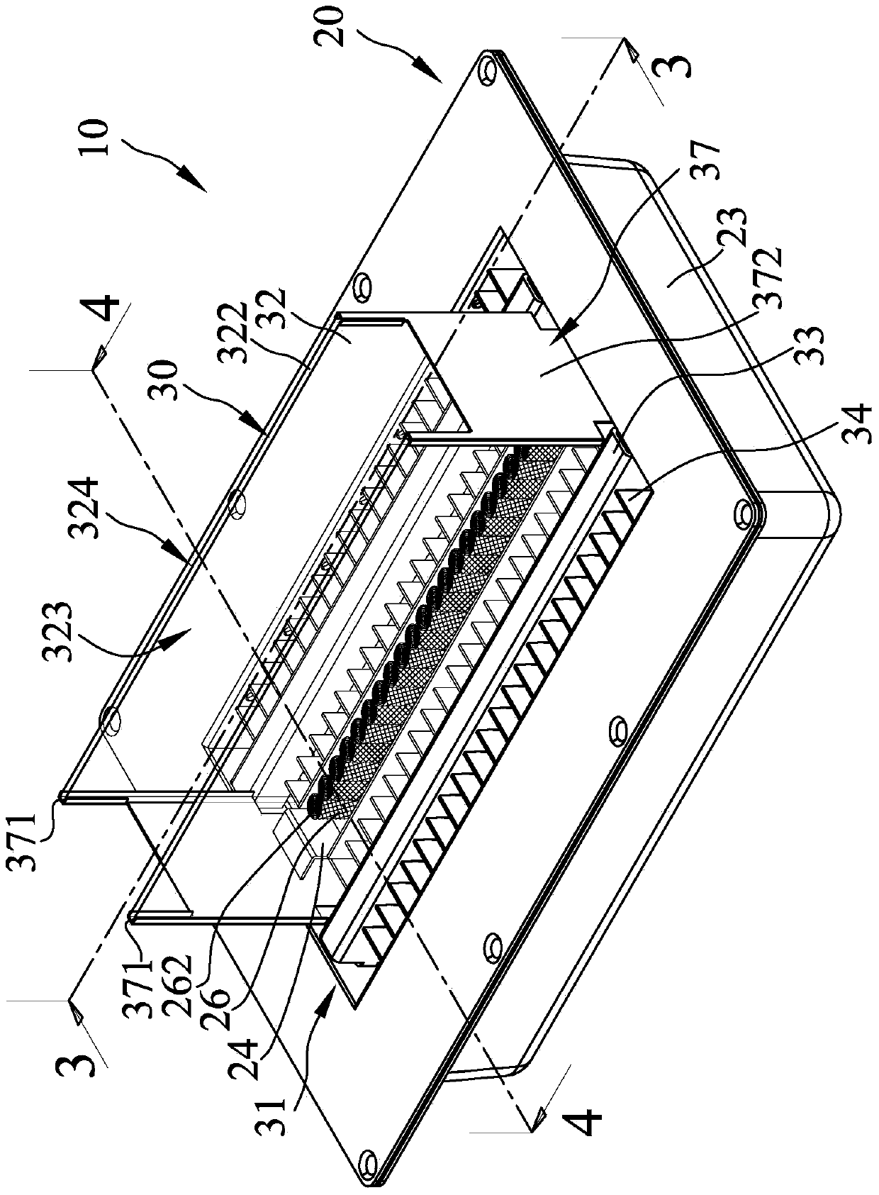
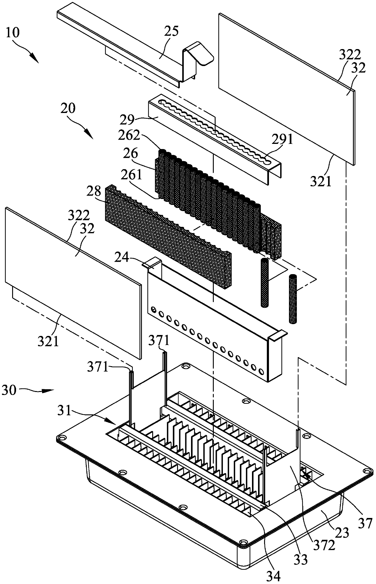
[0062] refer to figure 1 and figure 2 Shown is the three-dimensional appearance view and three-dimensional exploded view of the first embodiment of the safe combustion device of the present invention. The combustion device 10 of the present invention includes a body 20 and a flow guiding device 30; wherein:

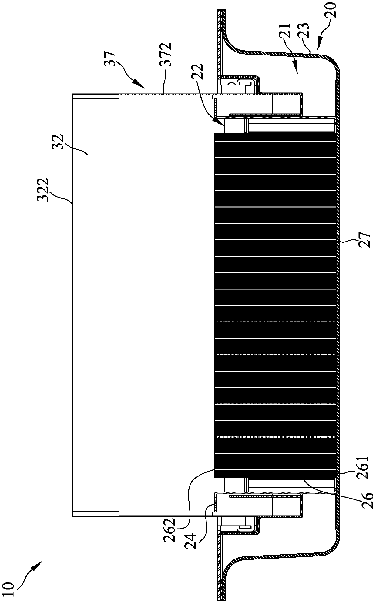
[0063] Please continue to refer to image 3 and Figure 4 Shown is the sectional structural view of the first embodiment of the safe combustion device of the present invention and the sectional structural view of another perspective. The main body 20 defines an accommodating space 21 , and the main body 20 has an opening 22 , and the opening 22 communicates the inside and the outside of the accommodating space 21 of the main body 20 . This body 20 comprises a fuel container 23 and a fixed seat 24, and this fuel container 23 can fill fuel 90 (as Figure 7 ), the fixing seat 24 is connected to the fuel container 23, the body 20 also includes a flameout cover 25, and t...


PUM


Abstract

The invention discloses a combustion device with safety. The combustion device comprises a body and a flow guiding device, wherein the body is provided with a containing space and a group of lampwick; the lampwick is arranged in the containing space; the body is provided with a bottom surface; the lampwick comprises a top end; a first distance is arranged between the top end and the bottom surface of the lampwick; the flow guiding device is connected to the body and comprises a first shielding part which comprises a bottom side and a top side; a second distance longer than the first distance is arranged between the bottom side and the bottom surface of the first shielding part; a third distance longer than the first distance is arranged between the top side and the bottom surface of the first shielding part; the flow guiding device also comprises a first airflow channel for communicating the inner side and the outer side of the first shielding part. The combustion device disclosed by the invention has the advantages that in combustion, air is sucked through the airflow channel, and not only is the combustion provided, but also the airflow is controlled to pass through the surface of the combustion device so as to provide cooling; the shape of flame is controlled and stabilized by a first flow guiding part.

Description

technical field [0001] The invention mainly discloses a combustion device, especially a safe combustion device. Background technique [0002] Generally, existing fuel combustion devices are divided into two types: direct combustion and use of wicks. If the fuel is flammable, it can be ignited with an open flame without a wick. Commonly used are bio-ethanol fireplace burners. Because the use of flammable fuel often leads to safety problems, in order to control combustion, although some designs use flammable fuel, they do not directly ignite when used, but use the wick to control the scale of combustion. However, if the fuel is flame retardant, the fuel must be ignited through the wick. The most common burning device using a wick is a lamp. It is common to set a high-temperature-resistant plate on the fuel container, and place a cotton fiber wick in the plate, so that one end of the wick naturally hangs into the fuel cup. That is, the cotton fiber wick can absorb the fuel ...

Claims


Application Information

Patent Timeline
IPC IPC(8): F23D3/02F23D3/18
Inventor 陈维隆
Owner PRO IRODA INDS
Learn More