
Method for injecting gaseous fuels into an internal combustion engine at high pressures

a gaseous fuel and high pressure technology, applied in the direction of fuel supply apparatus, fuel systems, mechanical apparatus, etc., can solve the problems of shock wave turbulence, achieve the effects of enhancing combustion, improving combustion, and increasing fuel mass flow and gas momentum

Active Publication Date: 2006-10-26
WESTPORT FUEL SYST CANADA INC
View PDF6 Cites 6 Cited by
  • Summary
  • Abstract
  • Description
  • Claims
  • Application Information

AI Technical Summary

Benefits of technology

[0012] The present method improves combustion, and provides greater fuel mass flow and gas momentum for a gaseous-fuelled direct injection internal combustion engine. By using the compressibility of gaseous fuels, the present method of using high pressure direct injection enhances combustion by enhancing mixing of the fuel, thereby reducing emissions further by ensuring more complete combustion. Also, by utilizing the compressibility of the gaseous fuel, the mass flow of fuel and momentum of the fuel can be increased resulting in more mixing of the fuel and the delivery of more power to the piston in a cycle of the engine when the additional fuel is burned within the combustion chamber.
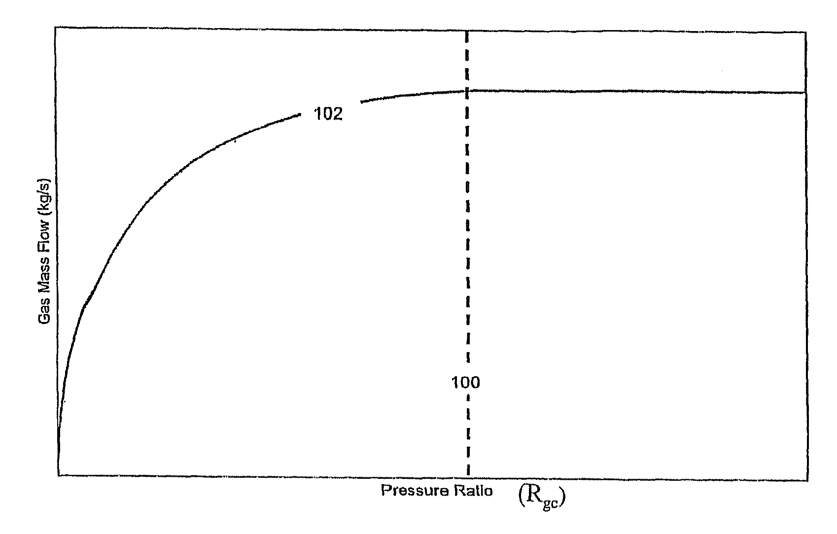
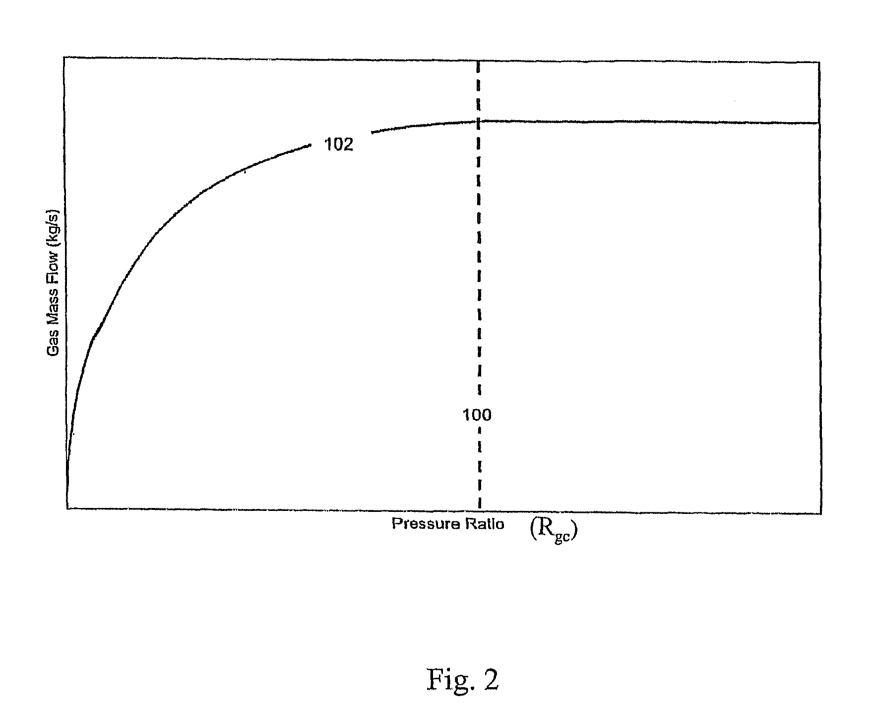
[0013] In particular, in the present technique, a gaseous fuel is injected into a combustion chamber of an internal combustion engine at a pressure resulting in a pressure ratio as a function of the injection pressure and the cylinder pressure in excess of a critical pressure ratio beyond which gas flow is choked (gas speed is sonic) at injector nozzle exit and the gas injection speed becomes supersonic after exit from the injector (that is, an under-expanded gas jet). The supersonic gas speed results in shock wave turbulence and mixing within the combustion chamber, which can promote combustion of the fuel.

Problems solved by technology

The supersonic gas speed results in shock wave turbulence and mixing within the combustion chamber, which can promote combustion of the fuel.

Method used


Image

  • Method for injecting gaseous fuels into an internal combustion engine at high pressures
  • Method for injecting gaseous fuels into an internal combustion engine at high pressures
  • Method for injecting gaseous fuels into an internal combustion engine at high pressures

Examples


Embodiment Construction

)

[0026] In the present method, a selected injection pressure for a gaseous fuel used in a gaseous-fuelled direct injection internal combustion engine is in excess of the critical pressure at which the fuel speed after exiting the injector nozzle exceeds sonic speeds within the combustion chamber charge. At increasing gas injection pressures the fuel density increases within the nozzle and fuel flow remains choked, with sonic speed maintained at the nozzle exit. However, upon exit from the nozzle, supersonic speed are reached as the gas is allowed to expand from the nozzle opening into the intake charge within the combustion chamber.

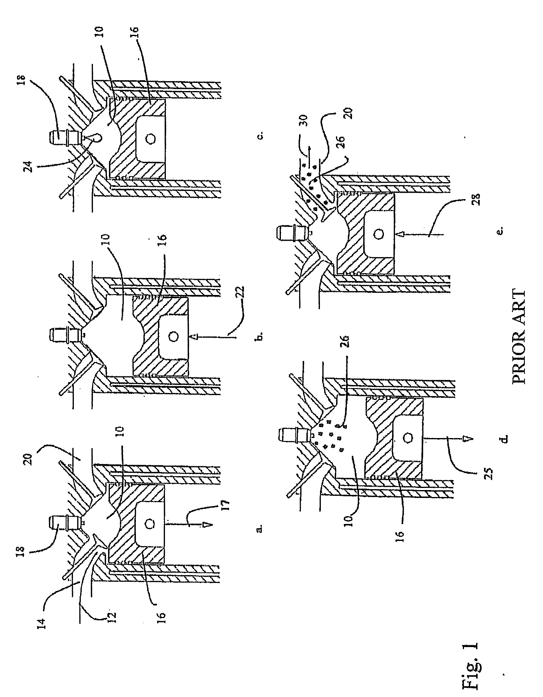
[0027] Referring to FIG. 1, a cross-section of a combustion chamber providing the stages in a cycle of a typical gaseous-fuelled direct injection engine is shown. FIG. 1a shows an intake charge introduced into combustion chamber 10 through intake line 14 in direction 12. At the same time, piston 16 is, during the intake stroke, moving in direction 17 awa...


PUM


Abstract

A method directly injects gaseous fuel into the combustion chamber of an internal combustion engine. The compressibility of the gaseous fuel is used to provide a fuel to the combustion chamber that is injected over all engine operating conditions at pressures that result in fuel jet speeds beyond the injector nozzle in excess of sonic speeds as determined in reference to the combustion chamber environment. The resulting fuel injection speed results in the fuel passing through shock waves within the combustion chamber, which, in turn, promotes combustion of the fuel by promoting turbulence and mixing of the fuel and intake charge within the combustion chamber where fuel burns in a non-premixed combustion mode.

Description

CROSS-REFERENCE TO RELATED APPLICATION(S) [0001] This application is a continuation of International Application No. PCT / CA2004 / 001767, having an international filing date of Sep. 30, 2004, entitled “Method For Injecting Gaseous Fuels Into An Internal Combustion Engine At High Pressures”. International Application No. PCT / CA2004 / 001767 claimed priority benefits, in turn, from Canadian Patent Application No. 2,443,474 filed Sep. 30, 2003, and Canadian Patent Application No. 2,463,791 filed Apr. 7, 2004. International Application No. PCT / CA2004 / 001767 is hereby incorporated by reference herein in its entirety.FIELD OF THE INVENTION [0002] The present invention relates to a method for directly injecting gaseous fuels into a combustion chamber of an internal combustion engine to promote combustion of the gaseous fuel. BACKGROUND OF THE INVENTION [0003] Because of its ready availability, low cost and potential for reducing emissions, gaseous fuels have long been a promising substitute fo...

Claims


Application Information

Patent Timeline
Patent Type & Authority Applications(United States)
IPC IPC(8): F02B3/08F02D19/02F02M21/02
CPCF02B2275/14Y02T10/123F02D19/024F02M21/0275F02D19/022Y02T10/32Y02T10/12Y02T10/30
Inventor MUNSHI, SANDEEP
Owner WESTPORT FUEL SYST CANADA INC
Learn More