Toroidal boundary layer gas turbine

a gas turbine and turbine technology, applied in the direction of machines/engines, mechanical equipment, lighting and heating apparatus, etc., can solve the problems of limited power output and efficiency of turbines and generators utilizing the boundary layer, and achieve the effects of increasing power output, reducing power consumption, and increasing efficiency

Inactive Publication Date: 2014-10-21
C6 COMBUSTION TECH LP
View PDF198 Cites 5 Cited by
  • Summary
  • Abstract
  • Description
  • Claims
  • Application Information

AI Technical Summary

Benefits of technology

[0005]By providing a combustion chamber extending about the circumference of the disc pack, a relatively simple construction permits considerable efficiency and power output. The configuration permits air and fuel to be mixed directly about the combustion chamber to ensure complete combustion of the fuel. This permits air and fuel to be mixed at a plurality of locations circumferentially about the chamber for increasing the power output by permitting more fuel to be consumed in an efficient manner and by imparting more rotational movement to the products of combustion.

Problems solved by technology

Prior art turbines and generators utilizing boundary layer effects to generate power, for example, those disclosed in U.S. Pat. No. 1,061,206 to Tesla and U.S. Pat. No. 7,341,424 to Dial, suffer from limited power output and efficiency.

Method used


Image

  • Toroidal boundary layer gas turbine
  • Toroidal boundary layer gas turbine
  • Toroidal boundary layer gas turbine

Examples


Embodiment Construction

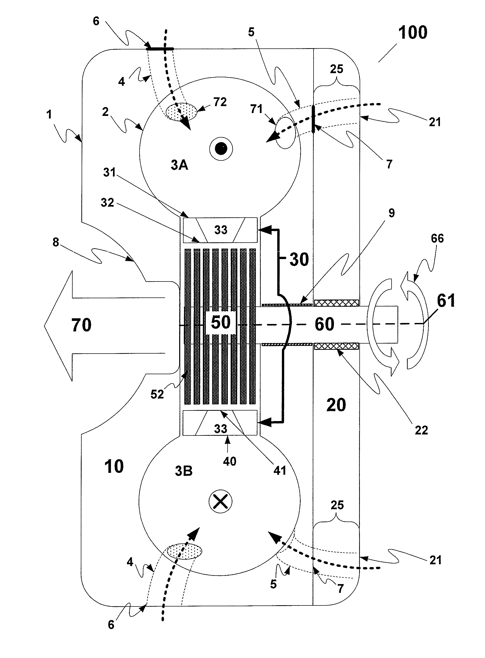
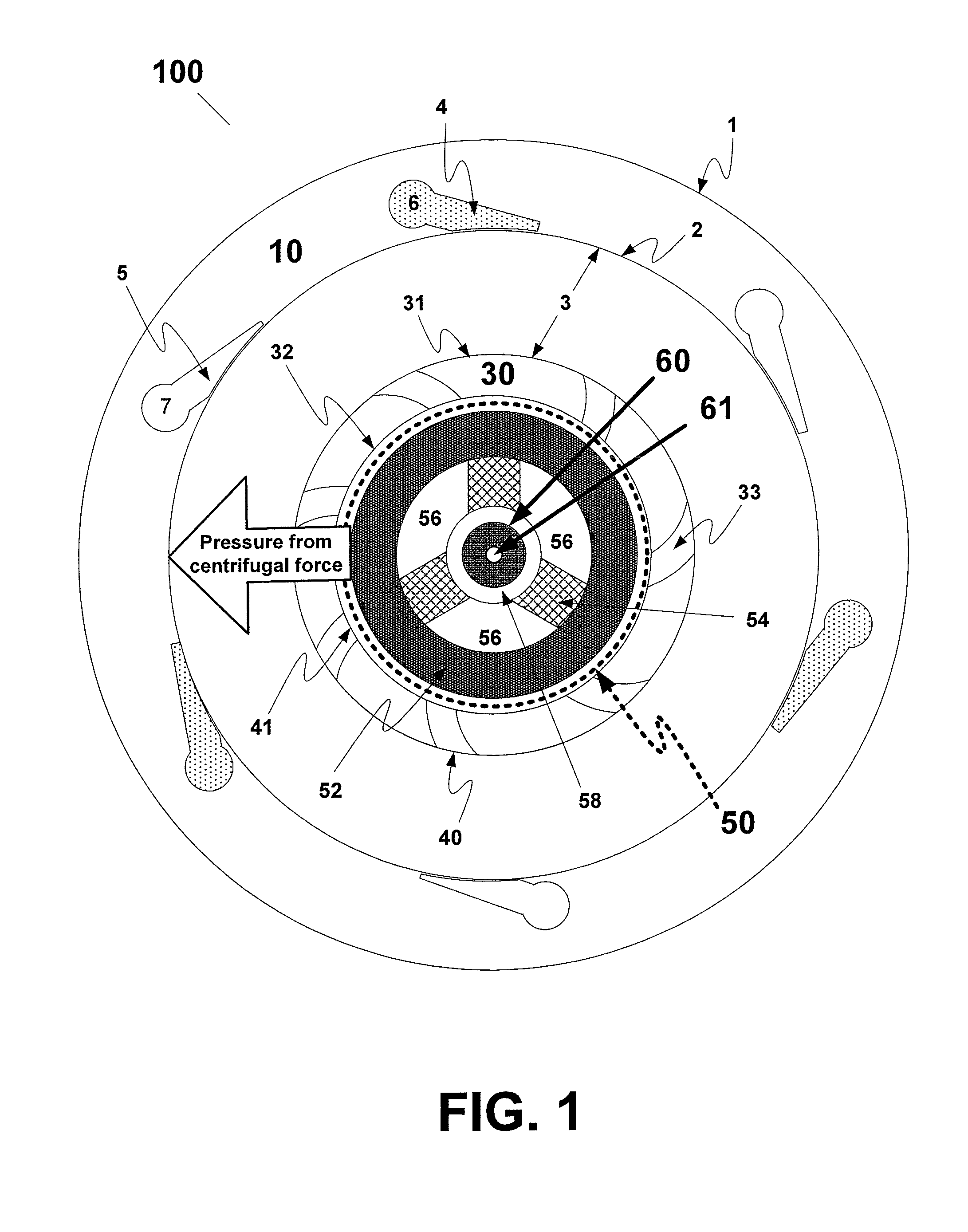
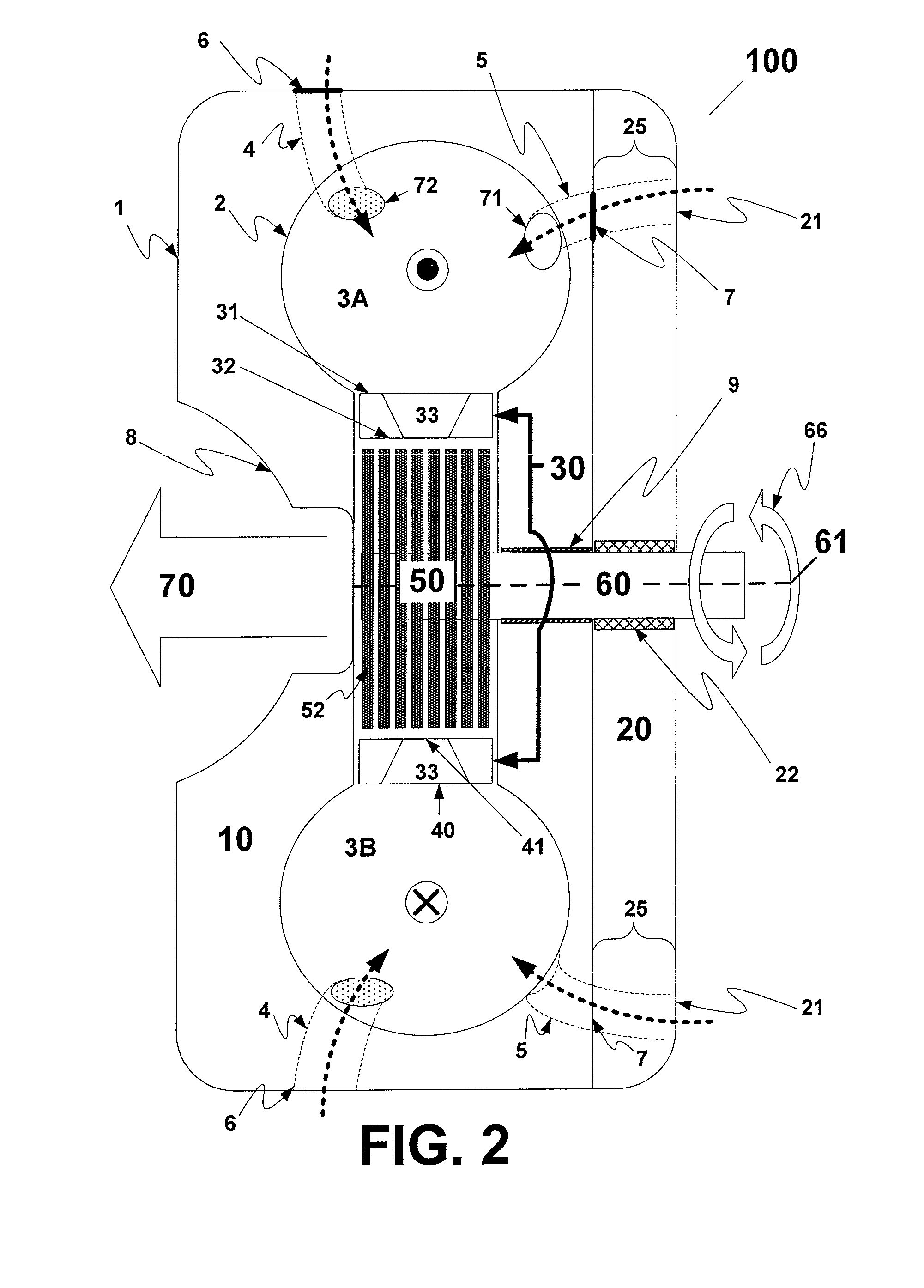
[0016]FIG. 1 illustrates a turbine 100, which may comprise a combustion housing 10, nozzle ring 30 and a disc pack 50. Disc pack 50 holds a drive shaft 60, such that the drive shaft 60 experiences the rotation of the disc pack 50. Disc pack 50 transfers power output from within turbine 100 to another device (for example, a generator or pump) via drive shaft 60. A turbine axis 61 is located at the geometric center of the face of drive shaft 60. The turbine axis longitudinally runs along the shaft 60.

[0017]Combustion housing 10 carries within itself a combustion chamber 3 located about the turbine axis 61 and through which combusted fluid travels to generate power via shaft 60. The combustion housing 10 has an outside surface 1 and an inside surface 2. According to an exemplary embodiment of the present invention, combustion housing 10 may be made or designed through known machining and / or molding processes with any material that can withstand high heat stresses and thermal shock, for...


PUM


Abstract

A device comprising a combustion toroid for receiving combustion-induced centrifugal forces therein to continuously combust fluids located therein and an outlet for exhaust from said combustion toroid.

Description

[0001]This application claims the benefit of the filing date of U.S. provisional patent application Ser. No. 61 / 109,660, filed on Oct. 30, 2008, the disclosures of which are incorporated herein by reference.FIELD OF THE INVENTION[0002]Disclosed are embodiments of the invention which relate to, among other things, turbines and methods of generating power.BACKGROUND[0003]Prior art turbines and generators utilizing boundary layer effects to generate power, for example, those disclosed in U.S. Pat. No. 1,061,206 to Tesla and U.S. Pat. No. 7,341,424 to Dial, suffer from limited power output and efficiency.[0004]Prior art turbines and generators relying on the teachings of Tesla have failed to take advantage of the simplicity of the Tesla design to generate maximized power output and there exists a need in the art for improved turbines and power generators.SUMMARY OF THE INVENTION[0005]By providing a combustion chamber extending about the circumference of the disc pack, a relatively simpl...

Claims


Application Information

Patent Timeline
Patent Type & Authority Patents(United States)
IPC IPC(8): F02C3/16F01D1/36F03B5/00F02C3/14F02C3/00F02K7/00F02C1/00F02C7/12
CPCF02K7/005F01D1/36F02C3/165F23R3/52F01D1/34F03B5/00F23R3/04F23R3/28Y02E10/20F23R3/34
Inventor BERGEN, ERNST
Owner C6 COMBUSTION TECH LP
Why Eureka
Try Eureka