
Connector

A technology for connectors and connecting parts, which is applied in the direction of connection, fixed connection, and installation of connecting parts, which can solve problems such as peeling of the grounding pad of the connector, deformation of the connector, etc., and achieve good contact and reduce the effect of force

Inactive Publication Date: 2011-12-28
AU OPTRONICS (XIAMEN) CORP +1
View PDF0 Cites 0 Cited by
  • Summary
  • Abstract
  • Description
  • Claims
  • Application Information

AI Technical Summary

Problems solved by technology

[0004] However, for the current existing LVDS cable connector, when the operator inserts the LVDS cable into the slot of the connector, the connector is prone to certain deformation due to the external force acting on the connector. In serious cases, such as excessive external force , will cause the ground pad of the connector to delaminate

Method used


Image

  • Connector
  • Connector
  • Connector

Examples


Embodiment Construction

[0018] The embodiments of the present invention will be clearly explained below with the accompanying drawings and detailed description. For the sake of simplifying the accompanying drawings, some known and commonly used structures and components will be shown in a simple and schematic manner in the accompanying drawings.

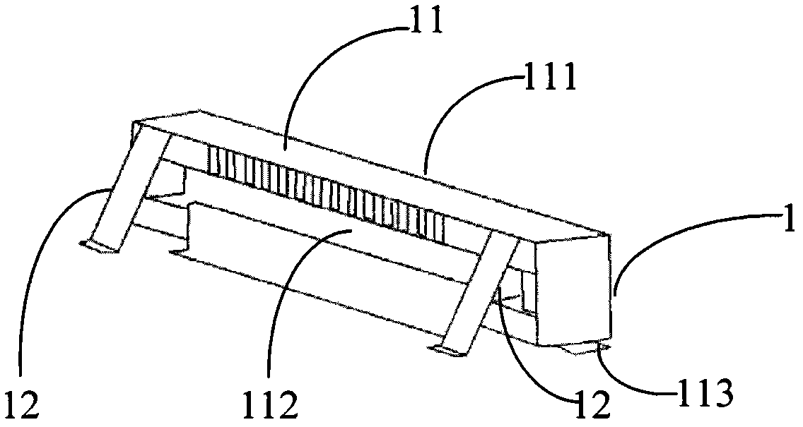
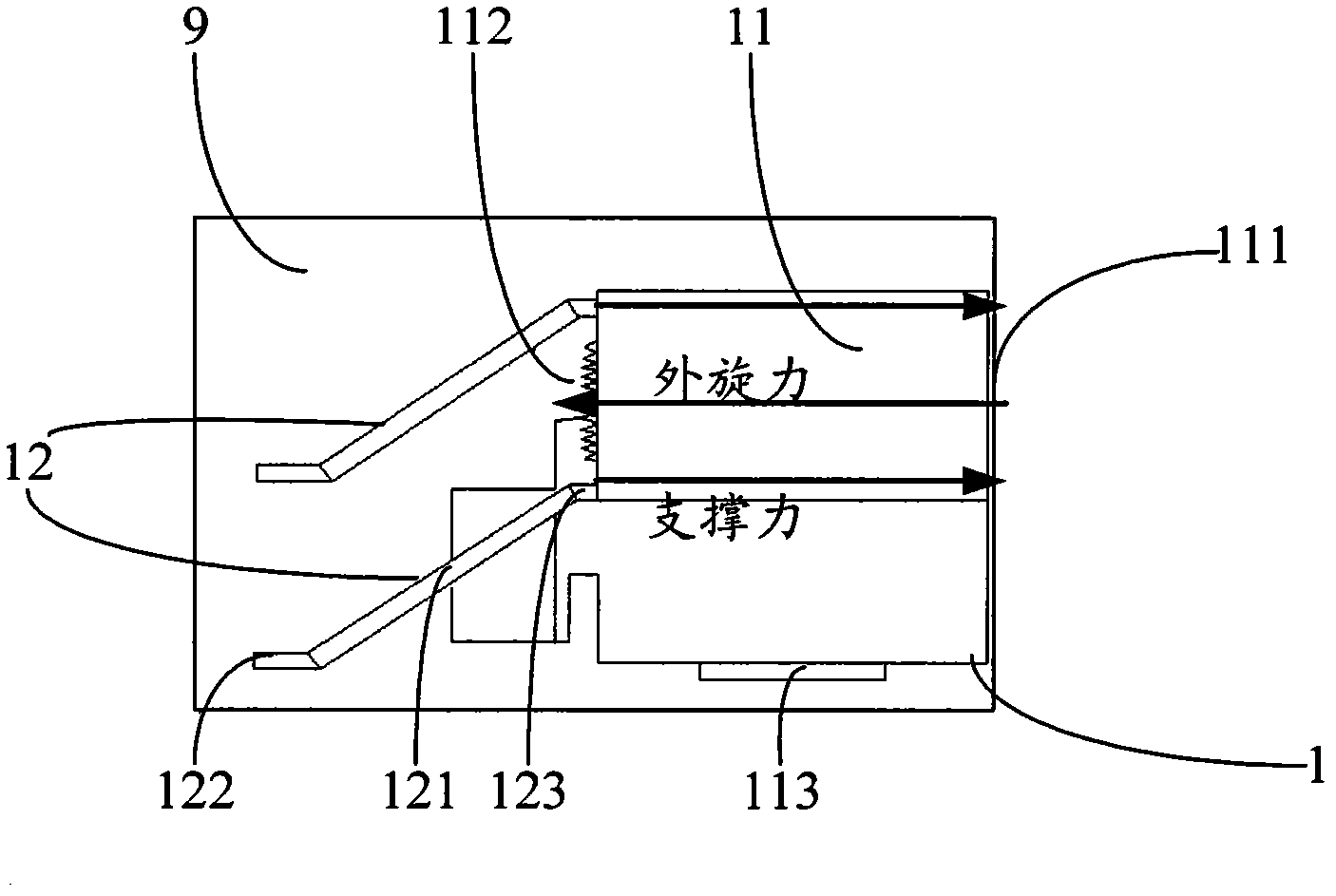
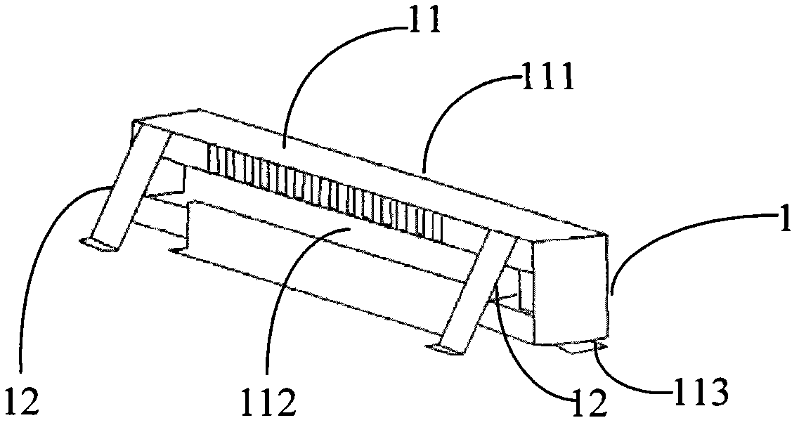
[0019] refer to figure 1 and figure 2 , figure 1 A schematic structural diagram of a connector according to an embodiment of the present invention is shown, figure 2 for figure 1 A structural schematic diagram of another angle of the depicted connector. like figure 1 and figure 2 As shown, the connector 1 includes a body 11 and two supports 12 . For the main body 11, it has a front end surface 111, a rear end surface 112 parallel to the front end surface 111, and a ground pad 113. The front end surface 111 has a plurality of slots (not shown in the figure), which can be used for low-voltage differential signal (Low-Voltage Differential Signaling, ...


PUM


Abstract

The present invention proposes a connector, comprising: a body having a front end surface and a rear end surface parallel to and opposite to the front end surface; two support members are obliquely arranged on a circuit board, and the support members include: a main body portion ; a first connecting portion extending from one end of the main body, the first connecting portion is fixedly connected to the circuit board; and a second connecting portion extending from the other end of the main body, the second connecting portion is fixedly connected to the body rear face. The connector proposed by the present invention has two supporting parts. When the connector is subjected to external force, the supporting part will generate a reaction force, so as to protect the connector from being deformed by external force, and reduce the size of the connector body and the circuit. The force on the soldering place of the board makes good contact between the connector and the circuit board.

Description

technical field [0001] The invention relates to a connector, in particular to a connector with a support. Background technique [0002] Currently, most TV LCMs (LCD Modules: Liquid Crystal Display Modules) need to be operated through a control panel and a motherboard, and are connected using Low-Voltage Differential Signaling (LVDS) cables when transmitting signals. Here, a liquid crystal display module is a component that assembles a liquid crystal display device, a connector, an integrated circuit, a PCB circuit board, a backlight source, and structural components, so it can also be called a "liquid crystal display component". [0003] In addition, LVDS is a new technology that meets today's high-performance data transmission applications. When used, it enables system supply voltages as low as 2V, providing designers with new options for solving high-speed I / O interface problems. For example, LVDS can provide a milliwatt-per-gigabit solution for high-bandwidth data trans...

Claims


Application Information

Patent Timeline
Patent Type & Authority Applications(China)
IPC IPC(8): H01R13/73H01R12/51
Inventor 朱仁煌
Owner AU OPTRONICS (XIAMEN) CORP
Learn More