
mems device and remote sensing system using the mems device

A sensing system and remote technology, applied in the field of sensing systems, can solve problems such as constraints and limitations of operating conditions

Inactive Publication Date: 2011-12-28
GENERAL ELECTRIC CO
View PDF1 Cites 14 Cited by
  • Summary
  • Abstract
  • Description
  • Claims
  • Application Information

AI Technical Summary

Problems solved by technology

The main disadvantage with such MEMS devices is that typically the operating conditions of the MEMS device are constrained by the operating conditions of the electronics
The sensing element of a MEMS device can itself withstand wider temperature, pressure ranges, or other harsh conditions, but the associated electronics impose limitations

Method used


Image

  • mems device and remote sensing system using the mems device
  • mems device and remote sensing system using the mems device
  • mems device and remote sensing system using the mems device

Examples


Embodiment Construction

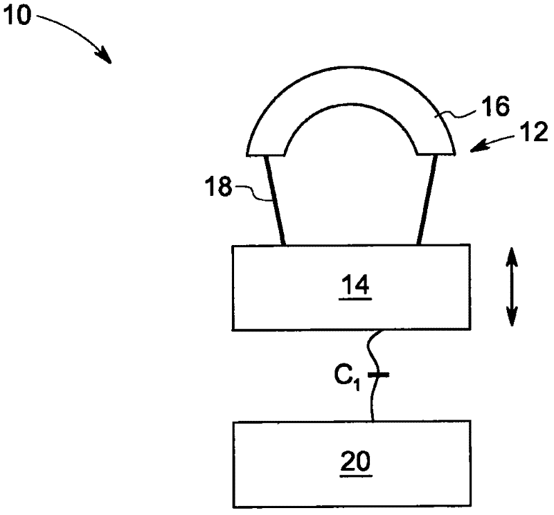
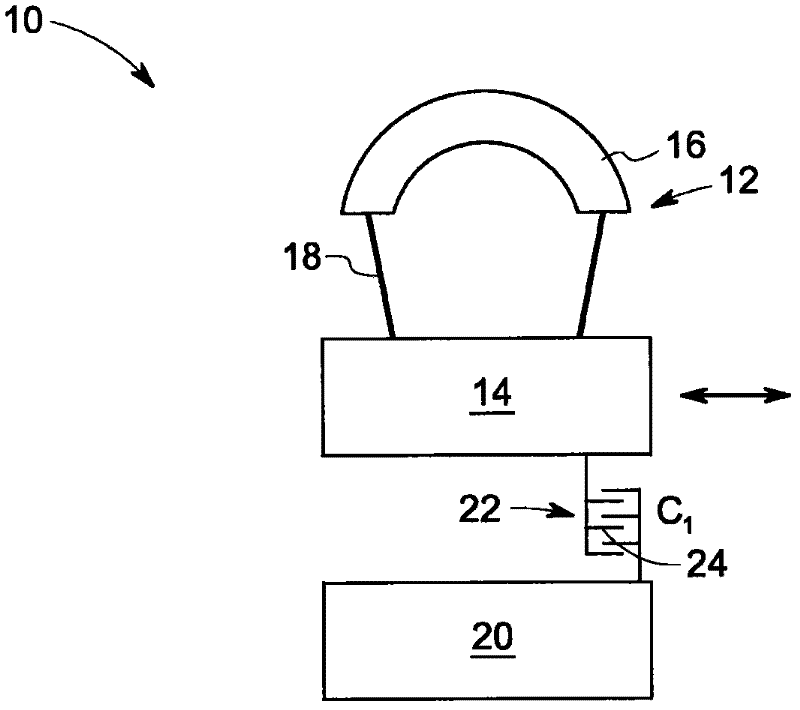
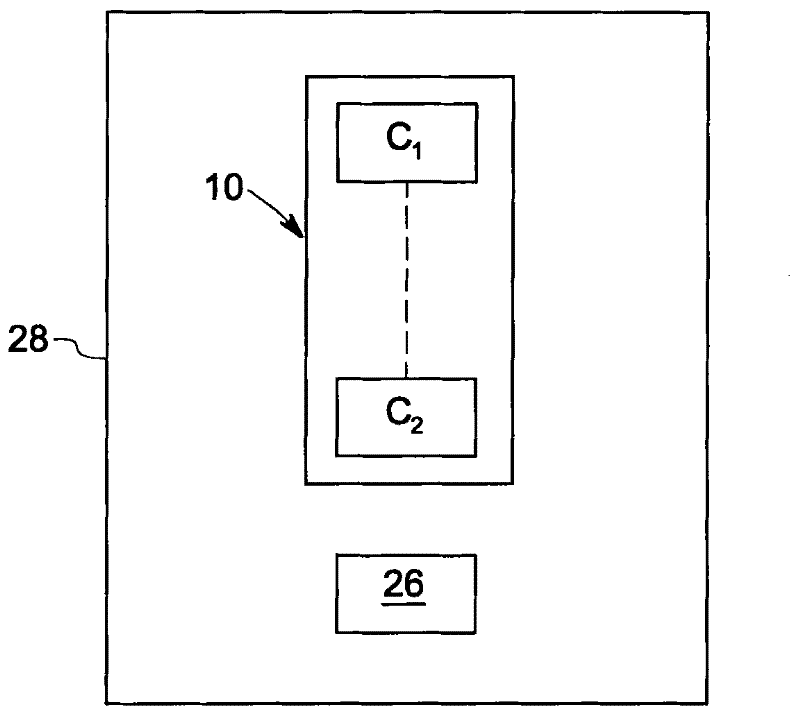
[0017] The embodiments disclosed herein include microelectromechanical sensor (MEMS) devices and remote sensing systems using MEMS devices. The sensing system is used to measure environmental conditions such as pressure or temperature exposed by the MEMS device. The MEMS device is placed where information about environmental conditions is needed. The sensing system includes an excitation element to drive the sensing element of the MEMS device to resonance, and a reader element to collect the frequency of the sensing element to determine the environmental conditions exposed by the MEMS device.

[0018] figure 1 The MEMS device 10 is shown. The MEMS device 10 is a passive sensor device (without any semiconductor junction or battery), and does not include an energy harvesting structure such as a solar cell or an acoustic scavenger that limits the operating temperature. The MEMS device 10 includes a sensing element 12 and may include a force capacitor C1. The sensor element 12 is ...


PUM


Abstract

A remote sensing system includes a microelectromechanical sensor (MEMS) device (including a sensing element) that is driven from a remote location at a resonant frequency by transmitting a signal including any of an acoustic signal, an optical signal, a radio frequency signal, or a magnetic induction signal A resonant actuating element, and a reader for reading the raw frequency of the sensing element from a remote location using a signal comprising any of an acoustic signal, an optical signal, a radio frequency signal, or a magnetically induced signal for determining a condition to which the MEMS device is exposed circuit.

Description

Technical field [0001] The present invention relates generally to sensing systems, and more particularly to microelectromechanical sensor (MEMS) devices and remote sensing systems using the MEMS devices. Background technique [0002] One of the important applications of MEMS devices is in measuring environmental conditions such as pressure and temperature. The mechanical properties of the sensing elements in MEMS devices change according to these environmental conditions that they try to measure. This change in mechanical characteristics affects the mechanical resonance of the device and the effect is used to measure the environmental condition. One type of MEMS device used to measure environmental conditions includes sensing elements integrated with electronics. The sensing element is generally a mechanical structure, and these electronic devices both cause the sensing element to vibrate and are used to measure the vibration frequency of the element. The vibration frequency o...

Claims


Application Information

Patent Timeline
Patent Type & Authority Applications(China)
IPC IPC(8): G01K1/02G01K7/32G01L9/00
CPCG01L9/0019G01D21/00G01L9/002G01K1/02G01K2215/00G01K7/32B81B7/00G01L9/00
Inventor D·W·塞克斯顿G·P·科斯特A·J·克诺布洛奇R·G·布朗D·W·费尔努伊
Owner GENERAL ELECTRIC CO
Learn More