
Method for measuring machine main shaft zero point and grinding head radius of computerized numerical control (CNC) grinding machine

A technology of machine tool spindle and CNC grinding machine, which is applied in the direction of grinding machine tool parts, grinding/polishing equipment, workpiece feed movement control, etc., which can solve the problem of large difference in curvature radius, increase of processing cycle, and poor accuracy and other issues to achieve the effect of improving processing efficiency and processing accuracy

Inactive Publication Date: 2012-01-04
SUZHOU UNIV
View PDF4 Cites 6 Cited by
  • Summary
  • Abstract
  • Description
  • Claims
  • Application Information

AI Technical Summary

Problems solved by technology

[0004] However, the method of modifying the radius of curvature and making compensation files based on the measurement error data not only increases the processing cycle, but also the accuracy cannot be achieved very well, especially the radius of curvature will be much worse than expected
This greatly affects the follow-up workload of spherical / aspheric mirror processing

Method used


Image

  • Method for measuring machine main shaft zero point and grinding head radius of computerized numerical control (CNC) grinding machine
  • Method for measuring machine main shaft zero point and grinding head radius of computerized numerical control (CNC) grinding machine
  • Method for measuring machine main shaft zero point and grinding head radius of computerized numerical control (CNC) grinding machine

Examples


Embodiment

[0072] Embodiment: Using the SGFM-120-I CNC aspheric milling machine, the processing equation is a high-order aspheric surface as shown below:

[0073]

[0074] in:

[0075] the

[0076] The parameter values ​​are shown in the table below:

[0077] R -36.36 K -15.03485 A 1 0 A 2 -2.9920397e-5 A 3 1.0705626e-7 A 4 -3.0291481e-10 A 5 6.0219855e-13 A 6 -7.6360963e-16 A 7 5.4817004e-19 A 8 -1.6855259e-22 A 9 0 A 10 0

[0078] The mechanical zero point provided by the milling machine is: 108.8722, and the radius of the grinding head is: 29.866.

[0079] The specific implementation steps are as follows:

[0080] (1) Compile the CNC machining code according to the parameters provided by the machine tool, and mill a plane mirror with a caliber of 100 (it is best to mill a plane mirror with the same caliber as the maximum diameter of the machine tool. The maximum diameter of this machine tool is 120, and the condition...


PUM


Abstract

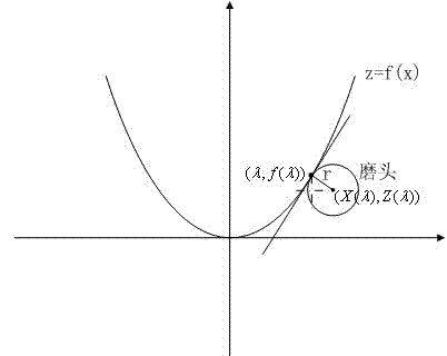
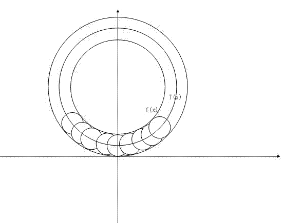
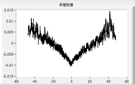
The invention discloses a method for measuring a machine main shaft zero point and a grinding head radius of a computerized numerical control (CNC) grinding machine. The method comprises the following steps of: (1) controlling the CNC grinding machine to grind a plane mirror, measuring the profile error data curve of the plane mirror, and making a reference compensation file of a guide rail according to measured error data; (2) compiling CNC codes aiming at a workpiece to be machined according to the zero point coordinate of a machine main shaft and data about the grinding head radius which are provided by a manufacturer, and the reference compensation file obtained in the step (1), and controlling the CNC grinding machine to machine and obtaining the rough-machined workpiece; (3) measuring the bus profile of the rough-machined workpiece by using a profile meter; and (4) analyzing the position of the zero point coordinate of the machine main shaft and the deviation of the grinding head radius by using data processing program which is compiled based on a data analysis model, according to the data about the bus profile obtained in the step (3) and the curve equation of the workpieceto the machined. According to the invention, the optimal values of the machine zero point and the grinding head radius of the CNC machine can be conveniently analyzed according to measured data of a machining workpiece, thus the machining accuracy is enhanced.

Description

technical field [0001] The invention relates to a detection method for a numerically controlled grinding machine, in particular to a method for accurately determining the coordinate position of the spindle center of the numerically controlled grinding machine and the radius of the grinding head according to the feedback information of the processed workpiece during the process of using the numerically controlled grinding machine to process spherical / aspherical optical elements , belongs to the field of mechanical manufacturing and optical cold processing. Background technique [0002] Machining spherical / aspheric surfaces with CNC grinding machines is a common technique in optical cold processing. In the process of generating CNC machining codes according to the machined surface shape, the distance between the spindle rotation center and the zero point of the grinding head (that is, the coordinates of the spindle rotation center in the machine tool coordinate system) and the...

Claims


Application Information

Patent Timeline
IPC IPC(8): B24B49/02
Inventor 仇谷烽余景池
Owner SUZHOU UNIV
Learn More